Hudson Jet |  |
DISCLAIMER: Unless otherwise noted, service information has been provided by an edition of the Mechanical Procedures Manual for Jet models. The data from the Manual includes information covering specifications, adjustments and detailed operation involved in maintenance and repair procedures. After market updates from Hudson Service Merchandisers and other sources have been added as well and are credited in italics. HudsonJet.net provides this reference as a courtesy and is not responsible for any work done using Hudson Motor Car Company's publications or other sources provided on this site. |
|
ELECTRICAL SYSTEM |
|
SPECIFICATIONS |
GENERATOR:
Make and Model............................
Type and Volts...............................
Control..........................................
Controlled Output...........................
Poles............................................
Brushes........................................
Brush Spring Tension.....................
Bearings:
Commutator End.....................
Drive End................................
Armature Shaft End Play................
Ground Polarity..............................
Field Coil Draw...............................
Motorizing Draw.............................
Output Test:
Cold.......................................
Hot.........................................
|
Auto-Lite GGW-4802A
Shunt - 6 Volt
Vibrating type current - Voltage Regulator
45 Amperes
2
2
35 to 53 ounces with new brushes
Bronze
Ball
.003" to .010"
Positive
1.4 to 1.5 amperes at 5.0 volts. Measure from armature to field terminals.
4.1 to 4.6 amperes at 5.0 volts. Have field grounded to frame and measure from armature terminal to a ground on the frame.
6.4 volts, 0 amperes at 870 to 970 RPM
8.0 volts, 45.0 amperes at 1925 to 2125 RPM
6.4 volts, 0 amperes at 950 to 1050 RPM
8.0 volts, 45.0 amperes at 2350 to 2550 RPM
|
GENERATOR REGULATOR:
Make and Model............................
Volts............................................
Ground Polarity.............................
Resistors:
R1.........................................
R2.........................................
Cutout Relay.................................
Armature Air Gap....................
Contact Point Gap..................
Contacts Close.......................
Contacts Open.......................
Current Regulator
Armature Gap.........................
Operating Amperage................
Armature Spring......................
Voltage Regulator:
Air Gap..................................
Armature Spring......................
Operating Voltage...................
|
Auto-Lite VBE-6104A
6
Positive
34.5 to 42.0 OHMS (Marked 38)
6.5 to 8.0 OHMS (Marked 7)
Resistance of voltage winding 29.8 to 33.0 ohms
.031" to .034" contacts should be open and the armature against the upper stop. Measure the gap with the gauge as near to the hinge as possible.
.015" minimum
6.3 to 6.8 Volts
4.1 to 4.8 Volts after a charge of 15 amperes
.048" to .052" contacts should be closed with the high limit gauge in place and open with the low limit gauge in place on the contact side and next to the brass armature stop pin.
43-47 (at 70°)
14-½ turns
.048" to .052"
14-½ turns
(at 22 ampere charging rate plus or minus 1.15 volts)
|
STARTER MOTOR:
Make and Model...........................
Volts.....................................
Poles....................................
Brushes................................
Brush Spring Tension..............
|
Auto-Lite MZ 4172 Auto-Lite MZ 4167
6 6
4 4
4 4
42 to 53 ounces 42 to 53 ounces
|
DISTRIBUTOR:
Make.............................................
Rotation.........................................
Drive..............................................
Point Gap......................................
Points Open..................................
Cam Angle....................................
Arm Spring Tension........................
Condenser Capacity.......................
Firing Order...................................
Shaft Bearings...............................
Shaft Side Play..............................
Shaft End Play...............................
Advance-
Timing Marks.................................
|
IAT-4016
Auto-Lite
Clockwise
Oil Pump
.020"
T.D.C.
39°
17-20 oz.
21-25 MFD
1-5-3-6-2-4
2 absorbent Bronze
.005" max.
.003" to .010"
Automatic Vacuum
0° at 300 RPM 0° at 5-¼"
1° at 350 RPM 1° at 5-¾"
4.5° at 500 RPM 4° at 7-½"
12° at 1325 RPM 6° at 8-¾
13.5° at 1500 RPM 7.5° at 9-½"
Allowable variation from curve, plus or minus 1°.
Vibration Dampener
|
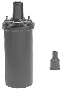
COIL:
Make.............................................
Model............................................
Amperage Draw:
Engine Stopped..............................
Engine Idling..................................
|
Auto-Lite
CR-6012A
5.0 amps.
1.5-2.0 amps.
|
SPARK PLUGS:
Make.............................................
Gap...............................................
Thread Size...................................
|
Champion H8
.032"
14 M.M.
|
BATTERY:
Make
Capacity
Number of Plates Per Cell
|
National 1W-90
90 Ampere hours at 20 hour rate
15
|
The starting system uses a 6 volt starter motor and left hand inboard type Bendix drive, on cars not equipped with Hydra-Matic Drive, and a right hand outboard Bendix Drive with cars equipped with Hydra-Matic Drive. The starter motor is energized by the battery through a solenoid. Turning ignition switch key to the extreme right activates the solenoid.
The battery [at time of original purchase was] a Nation, Model 1W-90, 45 plate 6 volts 90 ampere hour storage battery. The battery is located in the front left corner of the engine compartment and is held in its carrier by a metal frame and holddown bolts. It is easily accessible for servicing by raising the hood.
The service you receive from your battery depends on the care it is given. The battery should be kept clean and dry. Keep terminal connections tight and free from corrosion. Be sure the battery is properly secured in the carrier. If corrosion is present around the terminals, wash the affected aprts with a baking soda solution and then rinse off with clean water.
Low water level causes the plates to dry out resulting in premature battrey failure. Electrolyte level should be at the bottom of the square in filler cap opening. Keep the cells filled to the square by adding distilled water. Check level at least once a week. Level should be checked at lubrication periods and more often in warm weather.
NOTE: Winter driving conditinos create a heavier demand on the battery. When adding water in cold weather, do so immediately before driving the car or run the engine for a short time to insure that the water mixes properly with the battery solution. Unless this precaution is taken, freezing of the battery may result.
CAUTION: Storage batteries emit hydrogen gas which is highly inflammable during and after normal operation of the car. To prevent the possibility of fire or explosion, never permit an electric spark or open flame near the battery.
BATTERY TEST
HYDROMETER
Under normal conditions a hydrometer reading of the specific gravity of each cell will determine the state of charge. A specific gravity of 1270 at 70° F indicates a fully charged battery. A specific gravity of 1.130 indicates a fully discharged battery. If specific gravity varies more than 25 points between cells, recharge and retest or test under load.
VOLTMETER
A battery that fails to perform properly after charging should be tested with a voltmeter. Each cell should show two volts or over under no load, and the voltage across the terminal posts should be six bolts or over. If these readings cannot be obtained the battery should be replaced.
LOAD TEST
A load test should be amde to eliminate possibility of a weak cell. Use Battery-Starter Tester or a standard cell tester witha heavy shunt across the terminals. With the cell tester the difference between cells should be not more than 1.5 volts, and each cell should test at least 1.5 volts. With the Battery-Starter Tester, meter should show at least 4 volts at 300 amperes discharge.
If a tester is not available, a voltmeter may be connected across the battery terminals while engine is cranked with the starter motor.
Battery is serviceable if the starter cranks the engine at a good speed for 1/2 minute and the voltage does not fall below 4-½ volts. DO NOT CRANK MORE THAN ½ MINUTE WITHOUT ALLOWING THE STARTER MOTOR TO COOL.
A slow cranking speed or voltage lower than 4-½ indicates a weak cell or high resistance in the connections to the starter, and the battery cables should be checked and load test repeated.
BATTERY CABLE CHECK
- Connect a negative voltmeter load to the negative battery terminal and the positive lead to the starter motor terminal. Crank the motor with the starter. Voltage should not exceed .2 volts.
- Connect the positive voltmeter lead to the battery ground post and connect the negative lead to car frame. Crank the motor with the starter. Voltage should not exceed .2 volts.
- Connect positive voltmeter lead to car frame and negative lead to starter motor frame. Crank the motor with the starter. Voltage should not exceed .2 volts.
- If voltage loss is greater than above, terminal posts, ground strap and connections, and starter solenoid should be checked for high resistance.
- Connect the negative voltmeter lead of the starter motor tester to the starter switch terminal and the positive lead to the engine for a ground.
- With the ignition key off, engage the starter motor and note reading on the voltmeter. The cranking voltage should read 5 volts or more.
CAUTION: Crank engine intermittently (not more than 30 seconds) to prevent starter motor from overheating.
- If the voltmeter reading is less than 5 volts, check the battery cables and starter solenoid to determine the causes for the low reading.
|
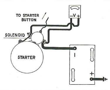
STARTER SOLENOID TEST
- Connect negative lead to "Bat" terminal of starter solenoid switch and positive lead to the starting motor terminal of starter solenoid switch, Figure 1 [at right].
- Close the solenoid electrically to crank the engine; if the reading is more than 0.2 volts, replace the solenoid switch.
STARTER REMOVAL
- Disconnect cable at battery negative terminal and remove cable at starter motor post.
- Remove the two starter mounting stud nuts and remove the starter motor assembly.
|
Figure 1
 |
DISASSEMBLY
- On cars equipped with the outboard type starter, remove the two through bolts attaching the Bendix housing to starter frame and remove the Bendix housing, drive out pin attaching adapter to shaft and remove adapter, sleeve and pinion.
- On inboard type Bendix, remove lock spring from end of Bendix drive, and remove spring and retainers.
- Remove two countersunk screws attaching drive end head and remove head.
- Remove commutator cover band and remove brushed from holders.
- Remove commutator end head and armature.
|
ASSEMBLY
- Replace armature in frame and install drive end head and attaching screws.
- Install commutator end head and through bolts and pry up brush springs and insert brushes in holders and replace band cover.
- Replace Bendix sleeve, pinion, spring retainer, spring, stop nut, pin and lock ring.
- On Hydra-Matic Drive equipped cars, install Bendix Drive Housing and through bolts.
INSTALLATION
Reverse procedure of removal.
|
Generator output is controlled by a three unit vibrating type current voltage regulator.
The voltage regulator holds the generator output at 45 amperes or below, depending on the load requirements.
A signal system incorporated in the regulator operates the signal light on the dash. The signal lights when the ignition switch is turned on and remains lighted until the generator starts to charge the battery.
The electrical system is positive grounded and whenever a generator is installed or reinstalled on the engine it should be polarized with the battery to prevent burning of regulator contact points and damage to the electrical units.
To polarize the generator, ground the field terminal to the frame and touch the armature lead briefly to negative terminal of the battery.
Generator brushes may be replaced without disassembling generator. Brushes should be replaced if they are oil soaked or worn to less than ½ of their original length.- Remove cover band and disconnect brush leads.
- Lift brush arms, remove old brushes, install new brushes in holders and connect brush leads.
- Cut a strip of 00 sandpaper the exact width of the commutator, slide sandpaper under brush with sanded side against brush.
- Pull the sandpaper so that brush is forced against holder. Once or twice is sufficient.
NOTE: Blow sand and carbon dust out of generator.
- Run generator under load to obtain perfect brush seating and re-install cover band.
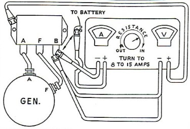
After generator is assembled and brushes properly fitted, the motorizing draw should be checked to assure proper assembly and alignment.
- Connect an ammeter and battery in series with the armature terminal and frame.
- Ground the field terminal and frame.
- Connect a variable resistor in series with the battery and generator.
- Connect a voltmeter from the armature to the frame.
- Generator should operate as a motor with the armature turning slowly.
- Adjust voltage to 5 volts and read ammeter.
- Motorizing draw should be 4.1 to 4.6 amperes. If motorizing draw is higher, or armature does not turn, worn bearing, incorrect bearing alignment, short circuits, or improper assembly is indicated.
|
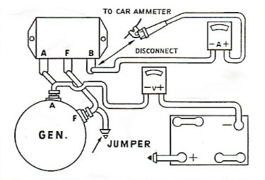
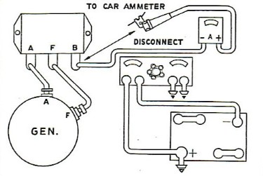
- Disconnect battery lead to voltage regulator "B" terminal; connect the ammeter negative lead to the regulator "B" terminal and the positive lead to the wire disconnected from the regulator, Figure 2.
- Install the negative voltmeter lead to the generator "A" terminal and the positive voltmeter lead to the battery negative terminal.
- Connect a jumper between the generator "F" terminal and a ground.
- Run the engine until ammeter shows 20 amperes. The voltmeter should not read over .9 (tenths) or less
|
Figure 2
 |
- If the resistance is more than .9, make the following checks with the ammeter connected as in paragraph 1.
- Remove the positive voltmeter lead from the battery and connect it to the "A" terminal at the voltage regulator. Ammeter should show less than .1 (tenth).
- Connect the voltmeter regative lead to the regulator "A" terminal and the voltmeter positive lead to the regulator "B" terminal. Ammeter should not show more than .3 (tenths).
- Next, connect the voltmeter positive lead to the battery regative terminal, negative lead to "B" terminal on regulator. Ammeter should not show more than .5 (tenths).
- Connect the voltmeter positive leads to engine ground, negative to base of regulator. Ammeter should show .2 (tenths) or less.
|
CIRCUIT BREAKER CHECK
To determine whether the circuit breaker points are closing at the proper generator voltage and also whether they will open upon deceleration by amperage from the battery proceed as follows:
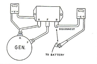
- Disconnect the battery wire at the voltage regulator "B" terminal and connect the ammeter between the voltage regulator "B" terminal and the wire disconnected, Figure 3 [right].
- Connect voltmeter positive lead to base of regulator and negative voltmeter lead to the generator "A" terminal.
- Set carburetor throttle lever adjusting screw so engine will idle at approximately 400 R.P.M.
- Increase engine R.P.M. by carefully rotating the accelerator bellcrank while watching the voltmeter gauge. When the voltmeter reads at any point between 6.3 to 6.8 volts the circuit breaker points should close and the ammeter will now show that the generator is charging.
- Next, slowly reduce the engine speed and watch the ammeter. When the ammeter reads 4 to 6 amperes, negative side of zero, the circuit breaker should open and the ammeter needle will return to zero. Perform operations 4 and 5 several times until you are sure your readings are correct.
- Proper adjustments can be amde by bending the spring hanger on the circuit breaker.
|
Figure 3
 |
- Disconnect the battery wire at the voltage regulator "B" terminal and connect the test ammeter between the voltage regualtor "B" terminal and the wire disconnected, Figure 4 [right].
- Connect the voltmeter positive lead to the regulator base and the negative lead to the regulator "B" terminal.
- Run engine approximately 2000 R.P.M.
- Vary resistance until ammeter reads 19 amperes and then check the voltmeter reading which should be 7.25 volts. (Hot, cover in place.)
NOTE: If car is out of warranty, the voltage regulator can be set by bending the spring hanger to get this necessary reading. The unit must be first checked with the voltage regulator cap in place as generally it will change the reading from.1 to .2 of a volt and must be compensated for in making this adjustment.
- Stop engine, disconnect battery negative terminal and then proceed to remove the tester leads from the voltage regulator and install the wires back onto the "B" terminal of the regulator.
- Install the regulator cover.
|
Figure 4
 |
CURRENT REGULATOR CHECK
- Disconnect the battery wire terminal "B" and connect the test ammeter between the voltage regulator "B" terminal and the wire disconnected, Figure 5.
- Connect a starter battery tester directly across the battery and set load to 45 amperes or use the equivalent in sealed beam lamps.
- Run engine to approximately 2000 R.P.M.; amperage reading should be 36 amperes. If it is not within a tolerance of one to two amperes of this reading, the regulator should be removed and taken to an authorized Auto-Lite dealer for replacement.
|
Figure 5
 |
NOTE: If car is out of warranty, remove the cover and adjust the current regulator spring hanger to the necessary 36 ampere output.
To prevent operation of the voltage regulator unit while making this adjustment place a jumper across the voltage regulator points. For final checking, the regulator cover must be in place on regulator.
CAUTION: Momentarily touch the negative battery cable to battery negative post to determine that there is no sparking between the battery negative post and cable terminal, then connect negative cable.
REGULATOR CONTACT POINTS
In normal use the contact points on all three regulator units will become grayed. If the contacts are burned, dirty, or rough, the points should be filed just enough to secure a smooth surface. File parallel with and lengthwise to the armature. Clean the points with a piece of linen or lintless bond tape dipped in carbon tetrachloride and follow with dry tape. use clean tape for each set of contacts.
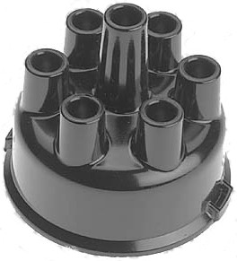
The distributor rotates in a clockwise direction. The distributor shaft has an offset tongue end which fits into a slot at the end of the oil pump shaft gear.
Incorporated in the distributor is an automatic centrifugal advance and vacuum advance control. The automatic centrifugal advance provides the proper ignition timing in relation to engine speed. The vacuum advance control provides additional spark advance over the centrifugal advance through te engine vacuum. When the engine is running under light load and engine vacuum is high, the breaker plate is rotated to the maximum advanced positions. However, under heavy load conditions, as when the throttle is opened for additional acceleration or hill climbing, the engine vacuum is low, the breaker plate is rotated to the retarded position to prevent detonation or pinging.
Correct spark setting is obtained when the number one cylinder is at top dead center on compression stroke, rotor facing No. 1 terminal of distributor cap, distributor set in midposition in the quadrant, and contact points just opening.
|
Breaker points may be adjusted with distributor isntalled in car as follows:
- Remove distributor cap and rotor.
- Crank engine until the fibre block on the contact arm rest on the highest point of the cam lobe.
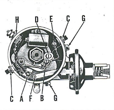
- Loosen the contact support lock screw (B) Figure 6 [right], and turn the eccentric adjusting screw (D) until the correct gap is obtained. Distributor point gap is .020".
- Tighten contact support lock screw and recheck point gap. If necessary bend stationary contact to secure correct alignment.
Webmaster's Note:All Hudson Distributors from 1933 thru to the end of Detroit production only had one set of points. There were some mechanics that felt that dual points were an advantage, and sold an adapter package to convert the standard Autolite distributors to dual points. |
Figure 6
 |
- Remove distributor cap and rotor
- Remove hairpin clip at (F), Figure 6 [above], screws (G) ataching vacuum control unit to distributor housing and remove vacuum control unit.
- Remove the two screws at (C) and the two nuts, washers and insulators at (H).
- Disconnect breaker point wires at (E) and (H) and remove complete contact support plate and contacts with condenser attached for bench disassembly.
- Remove screw and clip (A) attaching breaker arm spring and remove breaker arm spring.
- Remove locks crew (B) attaching stationary contact and remove the contact.
- Install a new breaker arm and attach primary and condenser lead wires to breaker spring clip and install clip and screw (A).
- Install a new stationary contact but do not tighten lock screw; connect wires at (E) and (H) and isntall condenser.
- Install complete contact support plate and stationary contact as an assembly and install screws (C) and terminal nuts (H).
- Check alignment of contact points. Bend the stationary contact arm if necessary to secure proper alignment and contact. DO NOT bend breaker arm.
- Tighten screw (D) and adjust breaker point gap.
- Check breaker arm spring tension. Hook a spring scale to the arm at the contact and pull at a right angle to the contact surface. Tension should be 17 to 20 ounces just as the contacts seperate.
- Adjust spring tension by loosening screw at (A), attaching breaker arm spring to plate, and move end of spring in or out of clip as necessary.
|
|
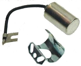
Check condenser lead to see that it is not frayed or broken and is connected securely to breaker arm clip. Condenser mounting screw must make tight ground to breaker plate. Ground wire from breaker plate to subplate must be securely connected. |
 |
DISTRIBUTOR REMOVAL
- Remove wires from distributor cap and remove cap.
- Disconnect vacuum line and the distributor primary wire.
- Remove the lock plate and the holddown screw attaching distributor quadrant to engine and remove distributor from engine.
|
 |
DISASSEMBLY
- Remove rotor.
NOTE: Remove stationary contact support with condenser, stationary contact and breaker arm as an assembly. See operations 2 through 4, under "Breaker Point Renewal". |
 |
- Remove oil wick from cam, remove hair pin retainer from oil well and pull cam off shaft.
- Remove centrifugal weights and springs, using care to prevent distortion of springs.
- Drive out pin from distributor shaft collar and remove shaft through top of distributor.
ASSEMBLY
- If clearance between shaft and bushings is greater than .005", install new shaft and bushings. Soak bushing in engine oil for 15 minutes before installing shaft.
- Install distributor shaft, thrust washers, collar and pin. Peen over pin.
- Check distributor shaft end play for minimum of .010" and install centrifugal weights and springs.
- Install cam, hairpin retainer, and oilwick. Apply a drop of engine oil to centrifugal weight pivots and cam slots.
- Pack breaker plate bearing ½ full of (high melting point) grease and install breaker plate, bearing retainers and breaker plate screws. Install breaker points and condenser on breaker plate before installing plate. Install plate and distributor cap screw. (Do not allow wire from breaker arm to primary terminal to ground on breaker plate.)
- Attach primary and condenser leads to clip (A) Figure 6 [above], on breaker arm spring and check spring tension. Adjust point gap.
- Install vacuum control unit.
NOTE: Make sure ground wire (E), is securely attached to upper and lower sections of breaker plate and that condenser lead and mounting are tight.
- Coat arm lobes lightly with water pump grease and soak the oil wick with engine oil. Place a drop of light engine oil on the breaker arm pivot and install rotor.
|
INSTALLATION
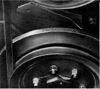
- Place a chalk mark on the long line before No. 1-U-D-C on the vibration dampener, Figure 7 [right].
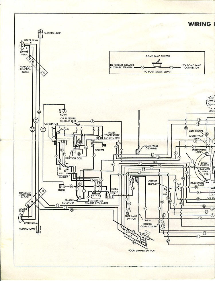
- Set distributor rotor to point to No. 1 contact in the distributor cap, Figure 8 [Electrical Wiring Diagram, below], and insert and engage distributor shaft in slot in oil pump gear.
- Install lock plate and hold down screw attaching distributor quadrant to engine. Set distributor midway on the quadrant and tighten screw.
- Replace distributor cap, secondary wire and spark plug wires.
- Place three to five drops of engine oil in shaft oiler and adjust timing.
For distributor testing and ignition timing, see Engine Tune-Up section.
|
Figure 7
|
Champion H-8 plugs are used. Gap should be .032". Check gap with a wirefeeler gauge and adjust by bending the ground (side) electrode. When replacing spark plugs always use new gaskets. Seat the plug finger tight and use a torque wrench to tighten to 25-30 ft. lbs.
|
If a faulty coil is suspected, the coil should be tested with a test light or approved coil testing equipment. A quick test with the coil on the car can be made by removing the high-tension wire from the center of the distributor cap and hold end of wire ¼" from cylinder head and while cranking engine if a spark occurs regularly the coil can be considered satisfactory.
|
 |
The headlamps are the "SEALED BEAM" type, designed so that the bulb, reflector, lens, and the gasket are assembled in one securely sealed unit making them dust and moisture free.
When the filament burns out or the lens break, the entire unit is discarded and a new one installed, thereby assuring maximum lighting efficiency. The Sealed Beam units are interchangeable right and left.
Two beams, controlled by the foot or dimmer switch are provided for highway illumination. The country (upper) beam throws the light a considerable distance ahead of the car while the traffic (lower) beam directs light low enough to avoid glare in the eyes of oncoming drivers. A red pilot light shows in the speedometer dial when the lights are in the upper beam position. Always use the lower beam when meeting oncoming traffic.
|
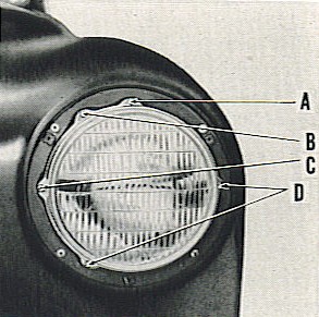
SEALED BEAM UNIT
REPLACEMENT
In the event that the unit burns out or is accidentally damaged, the entire sealed unit can be easily removed as follows:
- Remove headlamp lens rim by taking out the attachings screw(s).
- Take out the three screws (B) and (D), Figure 9, holding the retainer. Do not disturb the aiming screws (A) and (C) at the top and left side of the unit.
- Remove retainer by rotating counter clockwise, allowing the Sealed Beam Unit to be removed.
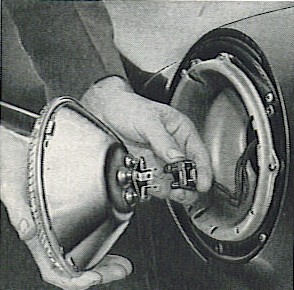
- Remove the reflector plug from the unit as shown in Figure 10.
- Install new unit by reversing above operation.
|
FIGURE 9
 |
HEADLIGHT AIMING
To obtain the maximum results in raod illumination and the safety taht has been built into the headlighting equipment, the headlamps must be properly aimed. Have them checked periodically. |
FIGURE 10
 |
ALL HUDSON MODELS 1948-1954
as suggested by A.E. Adams, Technical Service Editor,
in Technical Service Bulletin TS 77-1 by Hudson Motor Car Company, Detroit, Mich., U.S.A.
Reports from the field indicate that after twenty years or so of service it is not uncommon for the headlight switch to fail or the circuit breaker to cut the headlights off without warning.
The installation of a dual headlight relay will save the headlight switch and result in brighter headlights because there will be less voltage loss between the battery and the headlights.
The relay is installed between the headlights and the dimmer switch at a point close to the battery. When in operation the current flows directly from the battery through the relay to the headlights. It only takes a small amount of current to activate the relay; as a result the light switch does not
become overloaded causing the circuit breaker to cut out.
|
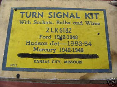
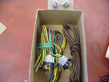
TURN SIGNAL KIT
Turn Signal Kits were available and NOS ones can still be found on rare occasion. These kits included bulbs, sockets, and wires. As seen in photo, the kit was also for Ford and Mercury vehicles dating 1942 through 1948. (Note that on Feb.9,1942 all United States automotive production stopped due to the war and didn't resume until July 1st of 1945, which may account for the length of time indicated on part run.)
|
 |
 |
The main circuit breaker is incorporated in the car headlight switch and is connected to an auxillary circuit breaker by a jumper wire.
The auxillary circuit breaker is located on the steering column brace under the dash panel.
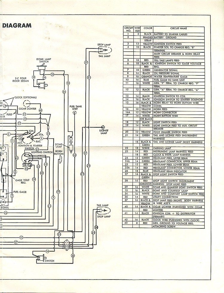
NOTE: When accessory items such as clocks or cigar lighters are installed, they must be connected as shown in the wiring diagram.
Fuses are used for the protection of optional equipment as follows:
- Electric Clock - Three ampere fuse in a fuse case at back of clock.
- Weather Control - Fourteen ampere fuse located in a fuse case on left side of weather-control housing.
- Radio - Fourteen ampere fuse contained in the fuse case on left side of radio or incorporated in the radio "A" lead wire.
- Direction Indicator - Ten ampere fuse attached to the flasher unit lead wire.
- Overdrive Circuit - Thirty ampere fuse located on Overdrive relay.
|
|
The horn is operated by a magnetic type motor which consists of a field, armature and a set of breaker points which interrupt the flow of current in the coil.
The armature is securely attached to the diaphragm.
Interruption of the current in the coil causes the diaphragm to vibrate which produces the sound.
The twin horns are constructed in such a manner as to produce different tone frequencies and the frequencies of each horn are synchronized to produce a harmonious tone when the horns are sounded together.
|
as suggested in Hudson Service Merchandiser Vol. 6, No. 1, January 1954
HORNET & WASP - 1954
Any one of the eight light bulbs may be replaced by reaching up behind the instrument panel.
To replace the speedometer, electric clock, fuel gauge, temperature gauge or voltage regulator, it is necessary to remove the instrument cluster. First, disconnent battery positive lead and disconnect speedometer. Remove eight 5/16" nuts from studs that hold the instrument cluster to dash. These are accessible without the necessity of removing radio.
Protect dash and shift control, leave all wires intact, laying instrument cluster backwith glass downward. Care must be exercised in the removal and installation of the speedometer, account of bending or damaging the indicator, to see that it lines up with the upper edge of rivet on speedometer face plate with approximately ½ inch clearance between the indicator and face plate.
When installing instrument cluster, tighten one stud, then check all lights and speedometer for operation.
To replace the instrument cluster glass, first remove as described above, then remove six metal screws which hold the glass retainer in position
JET - 1953 & 1954
The instrument cluster on the Jet for 1953 and 1954 may be laid back to make all instrument removal and installation accessible by first removing six nuts from ¼ inch studs. All instument light bulbs are removable from behind the instruments, and without removing the cluster, except the high beam indicator light bulb.
To remove this bulb, it is necessary to first unbolt and lay the instrument cluster back from the dash. Then remove the speedometer cover and two screws holding cover to speedometer.
In view of the inconvenience of replacing this bulb, be sure to use a Mazda 44 which is the longer life bulb.
The glass sections of any of the three instruments may be replaced by first removing the screws and retainers from the innder side - accessible only after laying the instument cluster back from the dash.
The antenna wire is a coaxial type, where the thin inner conductor has a fairly thick layer of insulation surrounding it, and a braided conductor "shield" layer near the surface. The inner conductor is usually connected to a short length of standard 14- or 16-gauge insulated hookup wire, soldered to the antenna itself. If you've removed your antenna and during install find that you can't resolder your orignial wire, finding a replacement Jet antenna will be your easiest swap. Otherwise, you may try pulling an antenna off an 80's or older "brand x" in a scrapyard for replacement wire. The radio end should have a plug-in connector like your Jet, but you'll hve to strip and resolder the other (center conductor) end onto your Jet antenna to be functional. Click here for printable Antenna Installation Instructions for the original roof-type antenna.
Once antenna and operating knob installation are complete, it's time to put it to the test. To raise antenna, press in knob slightly and turn to right or left one-half turn. To extend antenna, turn knob one-quarter turn, pull out inner or telescopic section of antenna and turn knob until antenna is in upright position.
FENDER ANTENNA INSTALLATION
- Spot and drill a 1¼" diameter hole in left front fender as shown in illustration.
- Loosen lower attaching bolts on left front fender splash shield, to permit access to space behind shield.
- Assemble coupling nut (A) of the lead cable to the nipple (B) on the antenna.
- Place swinging arms (C) on antenna, as shown on illustration.
- Insert antenna through opening between fender and splash shield. Lead cable connection and brace should point to front of car.
- Install the assembled rubber pad (B) and insulator (E) over the antenna.
- Install the cap nut (F) on the antenna and tighten finger tight.
- With the antenna vertical, bend anchor strap (G) around cowl side panel, drill a .136 hole and install sheet metal screw (S) as shown on illustration. This should secure the antenna in upright position. Tighten cap nut using a 1⅛" open end wrench.
- Pass antenna lead cable (H) into engine compartment and replace fender shield.
- Remove dash panel retainer, pass lead cable through grommet and replace retainer.
- Plug antenna cable into socket, on side of radio. Keep cable to top and front of radio.
- Drill .136 diameter holes in fender and hood side flanges as shown, and attach bonding cable (J) with self tapping scres (S). The bonding cable has been eliminated on later kits.
- Extend antenna completely and adjust antenna trimmer on radio for maximum volume, using a weak station near 1000 K.C.
- NOTE: On 4D, 5D and 7D Convertible Broughams and Hard Top Coupes, the antenna brackets are mounted to the pillar as shown. Two lead cables are also used on these Models.
|

|
While driving in the 50 to 60 mph range with my headlights on, the generator light has a slight glow of red. The lights are not dim and everything works fine. I cleaned the generator and put new brushes in it. Is this normal or do I have a charging problem?
If you haven't already read the Generator section above, please do so, as this answer will be reinforcement of the information already provided... A slight glow under those circumstances is normal. One side of the Generator light is connected to the ARM terminal of the Voltage Regulator (VR). The other side connects to the ignition switch, which is powered from a main circuit breaker under the dash which gets power from the battery. If several things feeding from that breaker or the ignition switch are operating (such as headlights, heater, etc.), the voltage at the ignition switch is pulled down a little, so there's a slight difference between the voltage there and down at the ARM terminal of the VR. That slight voltage difference is what causes the Gen light to glow slightly. Another cause can be bad contacts on the "cutout relay" in the VR, or improper or corroded connections at the VR. Any voltage loss in these places will be "felt" by the Generator light as well.
Furthermore, since the generator light is grounded through the armature, when the generator starts charging, the output cancels out the battery voltage. If the light is glowing, it indicates a voltage difference between the battery and the generator. This could just be dirty connections or resistance in the wiring. You need to check the generator output with an analog meter, at the "A" terminal, it should be 7.2 - 7.4 volts with the engine revving and the lights on. If it is at this level, don't worry about it.
If a new generator has been installed or the existing one reinstalled, it should be polarized, again outlined in the Generator section above.
Up until about 2 weeks ago I had an Amp light on in the dash when I turned the key. Once engine was running, the light went off. Now when I turn the key, no amp light, just oil. If the voltage at the generator reads 6.6, and at the regulator arm terminal 6.6, and the light is out after being on all this time, what might be the problem? I'm running an 8 volt battery, but doubt it ever gets charged to 8 volts, as I have to top it off all the time. Could that have burned out the lamp?
If you have 6 volts at the lamp, and it's not glowing, the bulb is blown. If you have an 8 volt abttery you will have to boot the charge rate up to at least 9 volts to keep it charged, and this may lead to blown bulbs.
My Jet cranks over way too slow, so only occasionally will it start. This is with a strong Optima 6 volt battery, new battery cables and a starter. Tthe electrical shop says is like new internally. What might be the problem?
Are the new battery cables large enough? The conductor its self, not counting insulation, should be 3/8" or larger. 00 is .365", 000 is .410".
Coil: Autolite CR-6012A, NAPA 1C7, Filco UC102, GP GC200, GP GC88, VallyForge GC40X, Hagens Auto Parts #E5
Breaker Points: BorgWarner I-85 Gp9305AS, Echlin CS719P or A, IGS 2224R5
Dimmer Switch: NAPA Echlin DS102
Distributor Cap: NAPA AL106, BorgWarner C143, Standard A1138, Autolite AIT-33, Hagens Auto Parts #C143
Door Jam Switch: Echlin DS106
Generator: Auto-Lite GGW-4802S
Headlight Switch: NAPA HL6362 (ECH)
Ignition Switch: 956-4704 (CHH) - Bailey Motors 800-394-8134
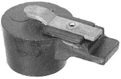
Rotor: NAPA AL112, BorgWarner D133, Surekit D133, Prestolite 4-2 (IAT-1016a), Hagens Auto Parts #D128
Spark Plugs: H10 Champion
Starters: Auto-Lite (w/hydra.trans) MZ-4172
Stoplight Switch: Wells F4805 - Discount Auto Parts
Voltage Reg: (orig.type) #VBE-6104AIH, Autolite VBE-6101A
Wiring Harnesses: Rhode Island Wiring for all Hudson wiring and YNZ Yesterdaysparts for select Hudsons.
|
 |
 |
|
|
|
Courtesy HET JetSet - All Rights Reserved.
|
|