The clutch for models is a single dry disc type. No adjustment for wear is provided in the clutch assembly. The adjustment to compensate for lining wear is provided by the clutch pedal linkage. Individual clutch release lever adjustments are made when the clutch is assembled but should never be disturbed except after disassembly for replacement of worn parts. A ball type clutch release bearing, prelubricated during manufacturing, is utilized and needs no additional lubrication. A steel clutch cover is bolted to the flywheel and contains the pressure plate, clutch pressure springs, clutch release levers and clutch drive plate.
|
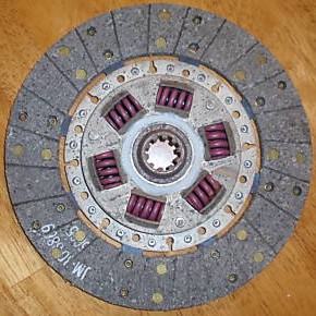
The clutch plate has molded woven asbestos facings riveted to both sides. Six dampening springs absorb shocks and cushions torque loads.
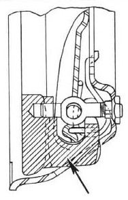
Pressure on operation of the clutch pedal moves the release bearing and collar assembly toward the release levers (5) which are pivoted on pins (8) in the eye bolts (9), adjustable to control release lever heights. Pivot pins float in the eye bolt bores to permit release lever movement. The outer ends of the release levers engage the pressure plate lugs through fulcrums (7) providing knife endged contacts between the levers and lugs, Figure 6.
|
CLUTCH PEDAL ADJUSTMENT
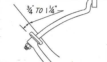
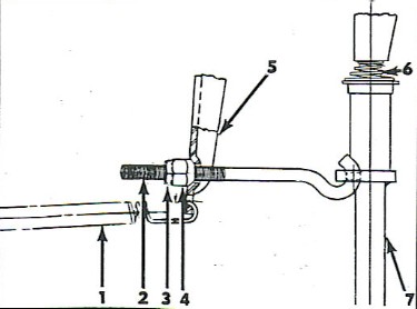
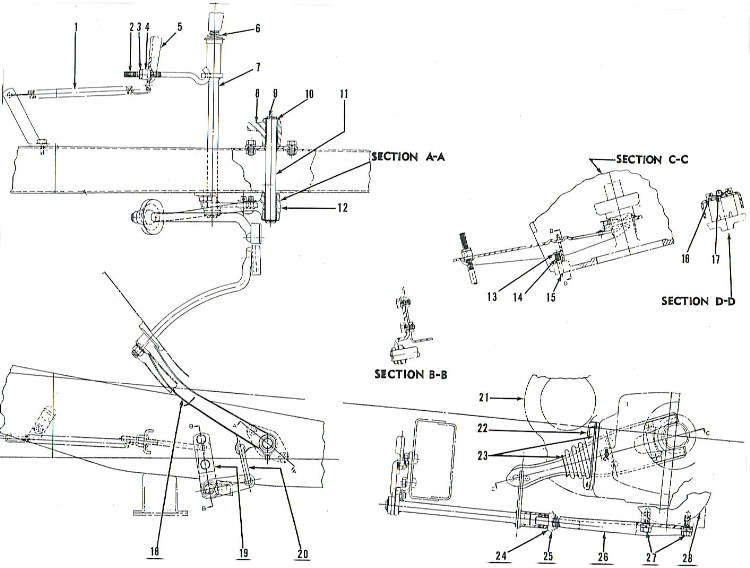
Full clutch disengagement must be provided to prevent gear clashing when shifting and to prevent the clutch pedal from riding against the floor boards. The clutch pedal clearance should be from 3/4" to 1-1/4", Figure 1. |
Figure 1
|
To adjsut the clutch pedal to maintain proper clearance proceed as follows:
- Loosen lock nut (3) Figure 2 on clutch adjusting link (2).
- Back off or tighten adjusting ut (4) to increase or decrease the clearance as required.
- Lock the adjusting nut (4) with lock nut (3).
|
Figure 2
|
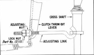
as suggested in Hudson Service Merchandiser Vol. 5, No. 9, September 1953
On investigation of reported cases of clutch pedal losing adjustment, it was found that the regular lock nut, Part No. 170228, used on the adjusting link, was not holding the adjusting nut.
An Engineering Change has specified the use of lock nut, Part No. 12115, to be used at this point (see illustration above), instead of lock nut, 170228.
In any case, where clutch pedal to floor board clearance does not hold at standard adjustment ¾ to 1¼ clearance, but is continually increasing, it may likely be due to the adjusting link lock nut not holding.
|
Figure 2 Amendment
|
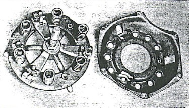
Figure 3 - Driven Disc Plate Assembly
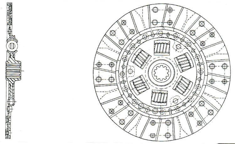 |
Figure 4
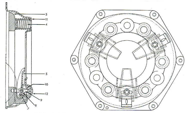 |
Figure 5
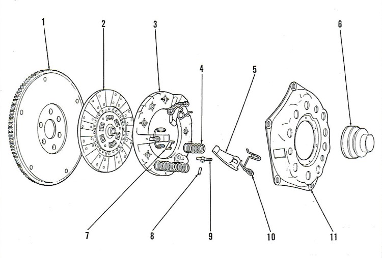 |
| LEGEND |
- Flywheel
- Driven disc plate assembly
- Less OD: Part# F 308373
- With OD: Part# F 308374
- Pressure plate: Part# F 307811
- Clutch engaging spring: Part# F 307818 - 6 per car
- Release lever (aka Throwout Finger):
Part# F 307812 - 3 per car
- Release bearing and collar
- Collar Assembly: Part# BT 308377
- Bearing: Part# F 308375
|
- Release lever retainer (Strut):
Part# BT 307816 - 3 per car
- Release lever eyebolt pin:
Part# BT 307813 - 3 per car
- Release lever eyebolt (Retainer & Nut):
Part# F 309242 - 3 per car
- Release lever anti-rattle spring:
Part# BT 307817 - 3 per car
- Clutch cover: Part# BT 307810
- Release lever eyebolt nut: See #9.
|
Figure 6
|
The clutch assemblies can be removed from the car without dismounting the clutch bell housing from the engine. The floor panel is welded in position and connot be removed. Therefore, all clutch work must be donw from beneath the car. To remove the clutch assembly from the car, proceed as follows:
- Raise the car and place jack stand under front suspension lower support arms.
- Disconnect the propeller shaft companion flange and remove the shaft.
- Disconnect the speedometer cable.
- Disconnect the shift selector levers from the transmission.
NOTE: Electrical wiring must be disconnected from the control switch, solenoid and governor and the wiring harness released from the clips on transmissions equipped with overdrive.
- Remove the two screws (27) attaching the clutch cross shaft support assembly (26) to the transmission and remove the support, Figure 6.
- Place transmission floor jack under the transmission.
- Disconnect the adjusting rod (2) from the outer end of the clutch throw-out lever (5).
- Remove the three attaching screws from the throw-out lever boot (22) and remove retainer and boot off the lever.
- Remove the four cap screws attaching the transmission to the clutch bell housing. Slide the transmission toward the rear of the car until the transmission main shaft clears the bell housing and lower carefully to the floor.
|
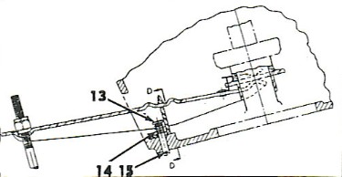
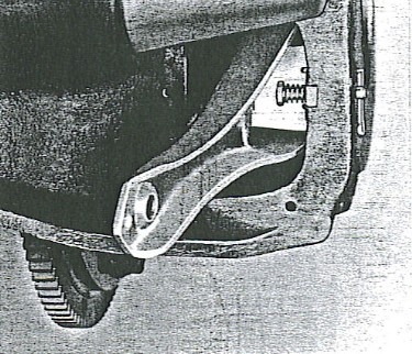
- Remove the cotter pin (15), pivot pin (13) and pivot pin spring (14) from the clutch bell housing and throw-out lever pivot, Figure 7. Remove the throw-out lever and the clutch release bearing assemblies from the bell housing.
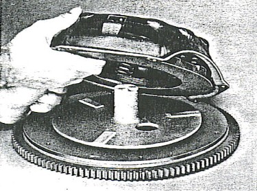
- Punch mark the clutch cover, pressure plate lug and flywheel for correct positioning during assembly.
- Remove the six cap screws attaching the clutch assembly to the flywheel and carefully remove the assembly.
NOTE: When removing the clutch assembly, loosen each cap screw only a few turns at a time until the spring tension is relieved. Otherwise distortion of the clutch cover might result leading to a chattering clutch condition when reassembled.
|
Figure 7
|
The clutch pressure plate and cover assembly is always under spring tension. Exercise care when disassembling the unit to avoid injury or damage to parts.
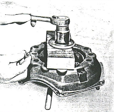
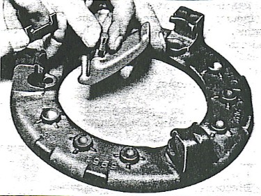
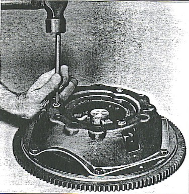
- Mount the clutch assembly on the clutch fixture or ona press. Place a wood block on the cover in position where it does not interfere with the three eyebolt nuts, Figure 8.
- Tighten the clutch fixture nut until the pressure springs are compressed sufficiently to relieve the rpessure on the release levers and remove the three eyebolt nuts, Figure 8.
- Loosen the clutch fixture nut carefully until the spring tension is relieved.
|
Figure 8
|
- Lift off the clutch cover and remove the pressure springs, Figure 9.
|
Figure 9
|
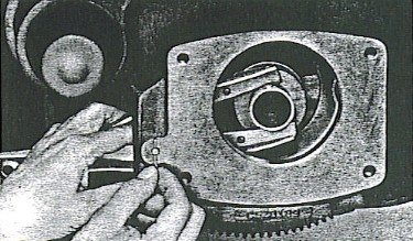
- Grasp the release lever and eyebolt between the thumb and fingers holding them close together. See Figure 10. With the eyebolt held in the pressure plate socket, lift the fulcrum over the end of the lever.
- Lift the eyebolt and release lever assembly out of the pressure plate socket.
|
Figure 10
|
INSPECTION
CLUTCH SPRINGS
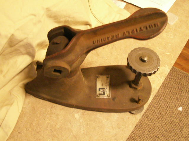
Clutch springs must be thoroughly inspected for cracks, burns and for proper tension at a given length. Use KMO-607 Valve and Clutch Spring Tester. 195 pound pressure plus or minus 6 pounds should be required to compress the spring to a height of 1-1/2".
Webmaster's Note:
Label of tester reads "Kent-Moore Org Inc. and Factories - Jackson Mich." It looks like it would be used with a torque wrench. The raised letters cast into it suggests that the torque reading should be multiplied by some number. Much more acurate tools are available now, but this one would make a neat display in a "period" work shop. Valued around $20.00?
|
 |
DRIVE PLATE
Repairs to the drive plate are not recommended except replacement of the facings. Carefully check for wear in the splines of the plate hub and for looseness of the dampening springs. Excessive wear of the splines or loose dampening springs may cause excessive back lash and noise.
When replacing worn facing, never punch the old rivets out as this might result in plate distortion. Use a 3/16" drill and cut away the rolled portion of the rivet and remove.
Rivet the new facings to the plate being certain they are held securely in position. Loose or uneven facings may cause the clutch to drag.
PRESSURE PLATE
The pressure plate must be true and free of scoring or cracks to provide smooth clutch application. Check for evidence of burning and overheating.
Place on a surface plate and check with feeler gauges to detect distortion. The maximum distortion should be no greater than .004" to .006".
Inspect the pressure plate lugs for wear at the fulcrum contacts. If excessive wear is noted the pressure plate must be replaced.
|
PRESSURE PLATE AMENDMENT
as suggested in Hudson Service Merchandiser Vol. 6, No. 6, June 1954
Outlined in the Jet Mechanical Procedure Manual are details pertaining to the assembly of the Dry Disc Clutch. Attention is called to the importance of applying lubricant to the clutch pressure plate and cover.
There have been instances of a pronounced squeak when the clutch is released or engaged. This was found to be caused by the movement of the pressure plate at the point where it contacts the side of the cover openings.
This may be corrected by the application of a very small amount of Hudson DGF Graphite Film Lubricant, Part No. HS-309909 at the point of contact. This may be reached by simply removing the clutch housing cover.
|
|
CLUTCH COVER
Care must be exercised during removal and installation of the clutch assembly. The clutch assembly is under spring tension and the six mounting screws attaching the cover to the flywheel must be loosened or tightened evenly to prevent cover distortion. If severe damage or distortion is noted replace the cover.
NOTE: The mounting screws are of a special hardened steel and in no case should substitutions be made.
After the clutch assembly has been removed from the flywheel, carefully inspect the surface of the flywheel for any roughness. Check the tightness of the flywheel stud nuts. Use a torque wrench and tighten to 40-45 foot pounds torque.
Check the crankshaft pilot bushings for looseness in the crankshaft bore and for scoring or excessive wear. If the bushing is badly worn it can be removed by using a 11/16" - 16 tap. As the tap is turned in, threads will be cut in the bushing. After the tap has bottomed in the crankshaft bore, the bushing will be forced out.
Install the new bushing in the crankshaft using tool J-5442.
The release lever fulcrums must be lubricated with a small amount of lubriplate grease before assembly. Below are the assembly steps:
- Mount the pressue plate on the clutch fixture, Figure 9.
- Assemble the release lever pin in the eyebolt and release lever.
- Hold the eyebolt and release lever upper ends as closely together as possible in one hand; then enter the lower end of the eyebolt in the pressure plate bore and install the fulcrum, Figure 10.
- Use the same procedure for installing the other two release lever assemblies.
- Check to see that the anti-rattle springs are in place in the cover. Figure 9.
- Place the six pressure springs, one on each plate boss, and install the cover over the springs. Be certain the springs seat in the cover recesses and the punch marks on the pressure plate and cover are aligned.
- Tighten the eyebolt nuts until they are flush with the upper ends of the eyebolts.
- Release the clutch assembly and remove from the clutch fixture.
|
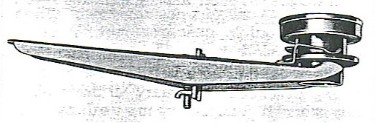
- Place the clutch Finger Adjusting Gauge J-4708, Figure 11 on a flywheel in the same position as the driven disc.
- Place the clutch assembly on the flywheel and align the machined surafaces of the gauge directly under the pressure plate levers. Tighten the cover mounting screws uniformly a few turns at a time until the cover is drawn down against the flywheel.
- Depress each lever several times before checking the lever height to seat the levers in their operating positions.
|
Figure 11
|
- After rechecking the lever heights to verify their setting stake the eyebolt nuts with a dull punch and a hammer, Figure 13.
- Remove the clutch assembly from the fixture. Always handle the Plate Gauge with care to prevent damage.
|
Figure 13
|
The clutch release mechanism, Figure 6, consists of the clutch throw-out lever (5), pivot (16), and linkage. The inner end of the throw-out lever contacts the flange of the throw-out collar. The clutch throw-out or release bearing fits over the inner end of the collar assembly and contacts the release levers when the clutch pedal is partially depressed, Figure 14.
The clutch release bearing is lubricated and sealed during manufacture. It should never be washed in gasoline or solvents. Solvents entering the bearing will dissolve the lubricant.
Check the bearing for roughness and wear. If found defective press the old bearing off the clutch collar and replace with a new bearing.
|
Figure 14
|
To install the clutch assembly on engine, proceed as outlined below:
- Place clutch assembly in position on flywheel with the driving plate between flywheel and pressure plate. Driving plate must be installed with side stamped "Flywheel side" toward flywheel.
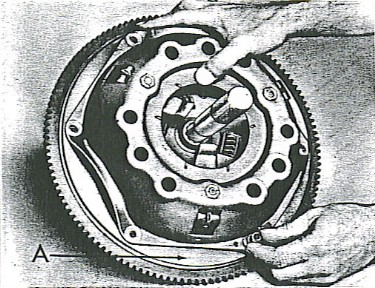
- Center the clutch disc on the flywheel using aligning arbor J-5442 or a transmission main drive gear shaft, Figure 15.
The clutch disc must be centered to permit entering the transmission main shaft in the driven plate hub splines. |
Figure 15
|
- Align the punch marks placed on the clutch cover and pressure plate hub with the one on the flywheel (A - Figure 15). Start the sex cap screws attaching the clutch assembly to the flywheel. Tighten the cap screws evenly a few turns at a time until the assembly is drawn up tight on the flywheel. Tighten the mounting screws to 20-25 foot pounds torque.
- Install the clutch throwout lever pivot 916) on the lever (5) and secure in position with the attaching spring (17), Figures 6 and 14.
- Hold the clutch release bearing toward the flywheel. Insert the throwout lever through the bell housing opening. The spring at the inner slotted end of the throwout lever will hold the thrust bearing assembly in place, (Figures 16 and 17).
The clutch disc must be centered to permit entering the transmission main shaft in the driven plate hub splines. |
Figure 16
|
- Hold the throwout lever and release bearing assembly in one hand and install the pivot spring on the throwout lever pivot pin. Insert the end of the pin through the bores in the pivot and the bell housing. Insert a cotter pin through the pivot pin and clinch securely.
- Raise the transmission, align the main shaft and slide the transmission forward against the bell housing.
- Install and tighten the four transmission holes to bell housing attaching screws and tighten to 35-40 pounds torque.
- Install throwout lever boot (23) and retainer (22), Figure 6.
- Connect transmission shift lever clutch control linkage speedometer cable and propeller shaft.
- Check for correct clutch pedal clearance (See Clutch Pedal Adjustment).
|
Figure 17
|