Hudson Jet |  |
DISCLAIMER: Unless otherwise noted, service information has been provided by an edition of the Mechanical Procedures Manual, Body Manual, and the Hudson Owner Manual for Jet models. The data from the Manuals includes information covering specifications, adjustments and detailed operation involved in maintenance and repair procedures. After market updates from Hudson Service Merchandisers and other sources have been added as well and are credited in italics. HudsonJet.net provides this reference as a courtesy and is not responsible for any work done using Hudson Motor Car Company's publications or other sources provided on this site. |
|
← Return to Servicing Index ←
- Check Arm
- Door to Body Alignment
- Front Door Complete
- Glass, Front Door
- Glass, Rear Door
- Glass, Quarter Window
- Handle, Outside
- Lock Cylinder
- Lock, Front Door
- Lock, Rear Door
- Lock, Release Push Button
- Lock, Release Push Button Adjustment
- Regulator, Front Window
- Regulator, Rear Window
- Regulator, Quarter Window
- Remote Control, Front or Rear
- Striker Plate
- Trim Panel, Door
- Ventilator Regulator, Front
- Ventilator Regulator, Rear
- Ventilator Wing, Front
- Ventilator Wing, Rear
- Weatherstrip, Front Door
- Weatherstrip, Rear Door
- Frequently Asked Questions
- Replacement Parts List
|
DOOR TRIM PANEL - Front and Rear, ALL Hudson Models 1948 thru 1954
REMOVAL
- Remove inside door handles.
- Remove lock release knob and garnish moulding, (on cars so equipped).
- Remove two screws from underside of arm rest and remove arm rest.
NOTE: On all 1953 and 1954 models the arm rest is part of the trim panel. Remove two screws from inside pocket of arm rest.
- Remove valance (on cars so equipped by extracting exposed screws and sliding valance up from between door and trim panel).
- Remove door pocket trim board (clips). (On cars so equipped.)
- Remove door panel held by (clips) using wide bladed putty knife.
INSTALLATION
- Repair any damage to door inside liner with Mystick tape before replacing trim panel.
- Install door trim panel by engaging the bottom retainer and aligning clips before driving panel into place.
- Install pocket trim board.
- Install valance by inserting lower flange between door and pocket trimboard; and, with slots in line with trimboard clips, force valance down into position and install screws.
- Install arm rest, (on cars so equipped), garnish moulding, lock release knob, and door handles.
|
REMOVAL
- Remove door trim panel. See "Trim Panel Removal", [above].
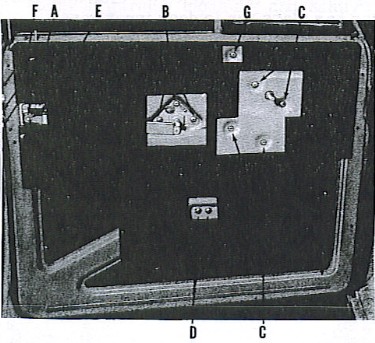
- Cut inner liner as shown in Figure 3, to expose screws (C) and hole (E).
- Remove retainer clip from the regulator arm to window glass channel.
- Raise the door glass, insert a drift or punch, through opening in door at (E) Figure 3, the drift should be so placed below glass channel to hold glass in a raised position when regulator is removed
- Remove screws (C) attaching regulator to door inner panel and remove the regulator through opening at bottom of door.
INSTALLATIONReverse the procedure of removal and repair door inner liner.
|
FIGURE 3
 |
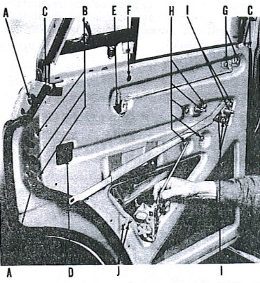
REMOVAL
- Remove door trim panel. See "Trim Panel Removal", [above].
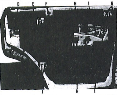
- Cut inner panel as shown in Figure 5, to expose screws (G) and (H).
- Remove the one screw (G)
- Remove retainer clip from the regulator arm to window glass control.
- Raise the door glass, insert a drift or punch through the opening where screw (G) has been removed. The drift should be so placed below glass channel to hold glass in a raised position when regulator is removed.
- Remove screws (H) attaching regulator to door inner panel and remove the regulator through opening at bottom of door.
INSTALLATION
Reverse procedure of removal and repair door inner liner.
|
FIGURE 5
 |
REMOVAL
- Remove rear seat cushion and back.
- Remove garnish moulding and regulator handle.
- Remove quarter trim panel.
- Lower quarter glass and remove the two retaining clips from the regulator arm and disconnect arm from glass channel.
- Cut inner liner to expose the four regulator attaching screws and remove screws.
- Remove regulator through lower opening in inner panel.
INSTALLATION
Reverse procedure of removal and repait any damage to panel inner liner.
|
REMOVAL
- Remove door trim panel. See "Trim Panel Removal", [above].
- Cut inner liner as shown in Figure 3, to expose screws (D).
- Remove the two screws (D) attaching center bar glass run to door inner panel.
- With the door glass in the down position, remove the retainer clip from the regulator arm.
- Remove the regulator arm from glass channel, bring the door galss down and at the same time turn the galss 1/4 turn to bring the anrrow side of glass to the top, as shown in Figure 6. Tilt glass inward and remove through the top opening in door.
INSTALLATION
To install, reverse procedure of removal.
|
FIGURE 6
 |
REMOVAL
- Remove door trim panel. See "Trim Panel Removal", [above].
- Cut inner liner as shown in Figure 5, to expose screws (J).
- Remove the two screws (J) attaching center bar glass run to door inner panel.
- With the door glass in the down position, remove the retainer clips from the regulator arm.
- Remove regulator arm from glass channel and bring the door glass down, at the same time, turn glass 1/4 turn to bring the narrow side of the glass to the top. Tilt glass inward and remove galss and glass channel through the top opening in door.
INSTALLATION
To install, reverse procedure of removal and repair any damage to door inner liner.
|
REMOVAL
- Remove rear seat cushion and back.
- Remove garnish moulding and regulator handle.
- Remove quarter trim panel.
- With quarter glass in the down position remove the two retaining clips from the regulator arm.
- Remove regulator arm from glass channel.
- Raise the quarter glass, tilt glass inward and remove through top opening in quarter panel.
INSTALLATION
Reverse procedure of removal.
|
REMOVAL
- Remove door window glass - follow operations (1), (3), (4) and (5) under "Door Glass Removal".
- Cut inner liner as shown in Figure 3, to expose screws (D) and (G).
- Remove screw (G) attaching wing frame to door inner panel.
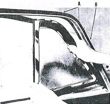
- Remove screws (A) and (B), Figure 8, attaching the wing frame to the upper door frame.
- Grasp center bar and pull back to dislodge wing frame from upper door frame, Figure 9.
- Pull inward and straight up to remove door wing frame, glass and center bar glass run as an assembly.
INSTALLATION
To install, reverse procedure of removal, repair damage to inner liner.
|
FIGURE 8
 |
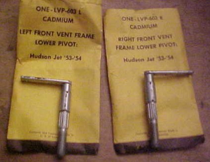
As labeled on package, photo at right shows both a Left and Right Front Vent Frame Lower Pivot. This is the part that holds the bottom of the vent window and keeps tension on the vent so it stays open. Notorious for rusting.
|
FIGURE 8B
 |
REMOVAL
- Remove door window glass - follow operations (1), (3), (4) and (5) under "Door Glass Removal".
- Cut inner liner as shown in Figure 5, to expose screws (F) and (J).
- Remove screw (F) attaching wing frame to door inner panel.
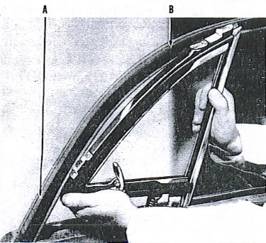
- Remove screws (A) and (B), Figure 8, attaching the wing frame to the upper door frame.
- Grasp door glass center bar and pull back to dislodge wing frame from upper door frame, Figure 9.
- Pull inward and straight up to remove door wing frame, glass and center bar glass run channel as an assembly.
INSTALLATION
Reverse procedure of removal and repair door inner liner.
|
FIGURE 9
 |
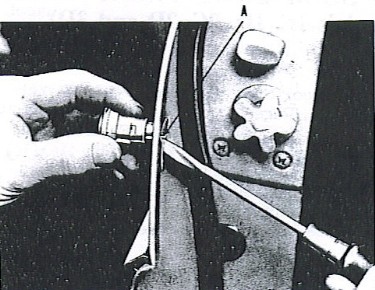
DOOR LOCK CYLINDER - ALL Hudson Models 1948 thru 1954
REMOVAL
- Insert a screw driver between the flanged end of the lock retainer and door panel and pry retainer (B), Figure 10 and (A), Figure 11, outward.
- Pull out lock cylinder assembly.
|
FIGURE 10
 |
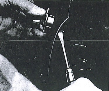
INSTALLATION
- From inside of door, insert a piece of pointed spring steel wire through the hole (C), Figure 10, in the door to the outside panel.
- Place recessed end of lock on the point of the wire, pilot the lock cylinder shaft, at the same time withdrawing the wire.
- With lock cylinder in position, install the lock retainer.
|
FIGURE 11
 |
REMOVAL
- Remove door trim panel, see "Trim Panel Removal". [above].
- Cut inner liner as shown in Figure 3, to expose screws (D).
- Remove window glass - follow operations (3), (4) and (5) under "Door Glass Removal".
- Remove retainer clip from door lock cylinder, see "Lock Cylinder Removal", Figure 11.
- Remove retainer spring (A), attaching the remote control link to door lock, Figure 12.
- Remove two screws (H), attaching the upper door frame to door assembly.
- Remove three screws (F), attaching the door lock to door assembly.
- From inside of door, pull back on upper door frame, push door lock inward and down.
- Turn lock 1/4 turn to by-pass upper door frame anchor plate and remove lock through bottom opening in door.
INSTALLATION
- Reverse procedure of removal, repair door inner liner.
- Install door trim panel. See "Trim Panel Installation".
|
FIGURE 12
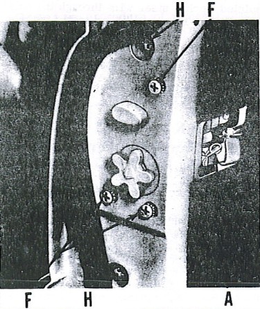 |
REMOVAL
- Remove door trim panel. See "Trim Panel Removal".
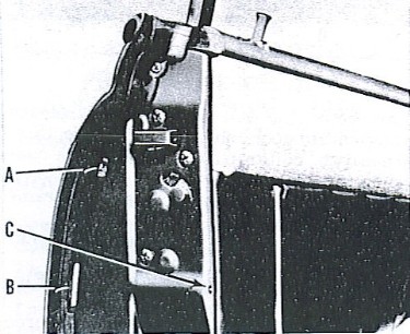
- Cut inner liner as shown in Figure 5, to expose screws (D), (E), (F) and (J).
- Remove retainer spring (D), attaching remote control link to door lock.
- Remove screw (A) attaching lock release rod pivot to door inner panel, Figure 13.
- Remove cotter pin attaching lock connector rod to pivot.
- Remove screw (F) attaching wing frame to door inner panel.
- Remove two screws (J) attaching center bar glass run to door inner panel.
- Cut weather strip at (C) as shown in Figure 13.
- Remove two screws at (A) and the three screws at the front section of the door attaching the upper door frame to the door assembly.
- With door glass in the raised position, raise the upper door frame approximately four inches to allow clearance to remove the rear door lock assembly.
- Remove three screws at (B) attaching door lock to door panel and remove lock through bottom opening in door.
INSTALLATION
Reverse procedure of removal, use rubber cement to join weatherstrip at points where it was cut. Repair any damage to door inner liner.
|
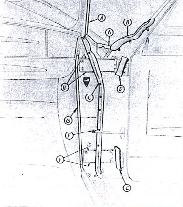
FIGURE 13
 |
REMOVAL
- Remove door trim panel. See "Trim Panel Removal".
- Cut inner liner as shown in Figure 3, for the front door to expose screws (B) and retainer spring (A) for the front door, or Figure 5, to expose screws (K) and retainer spring (D) for the rear door.
- Remove the three Phillips head screws attaching the triangular bracket of the remote control arm to door inner panel.
- Remove retainer spring from lock end of remote control arm.
- Withdraw remote control toward hinge side of door.
INSTALLATION
Reverse procedure of removal. Repair door inner liner with Mystik tape.
|
DOOR LOCK RELEASE PUSH BUTTON
REMOVAL
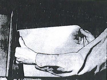
- Through the access hole in the door behind the weatherstrip, insert a screw driver as shown in Figure 15, and pry out push button.
NOTE: The door push button retainer also can be removed at this time.
INSTALLATION
- With retainer in position, line up door push button and snap retainer into position.
- Reglue weatherstrip as necessary.
|
FIGURE 15
 |
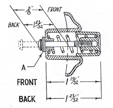
DOOR LOCK RELEASE PUSH BUTTON ADJUSTMENT
also suggested in Hudson Service Merchandiser Vol. 5, No. 9, September 1953
The proper operation of the front and rear door push buttons is obtained when the measurements are made as shown in Figure 20.
The measurement at upper left is obtained by adding washers (Hudson Part Number 171647) 1/32" thick as required, at point "A". The measurement shown [at right] is controlled by the threaded plunger and button. The object is to effect a door release before the button outer end passes into the retainer.
Removal of the front and rear push button assemblies is by inserting a screwdriver through access hole in door behind weatherstrip, illustrated at left above. Installation is by placing a cloth-covered tube over push button, line up key with groove in door opening and snap into position. Re-glue weatherstrip as necessary.
|
FIGURE 20
 |
DOOR OUTSIDE HANDLE
REMOVAL
- Through the access hole (A) in the door, Figure 16, remove the door handle retaining screw attaching door handle to door outside panel.
- Pull handle forward and out.
INSTALLATION
To install, reverse procedure of removal.
|
FIGURE 16
 |
DOOR STRIKER PLATE
The door striker, Figure 22, is mounted on the body pillar and is attached to a tapping plate on the inside of the pillar.
REMOVAL
Remove two Phillips head screws from the door striker and remove the striker assembly.
|
FIGURE 22
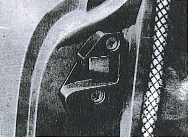 |
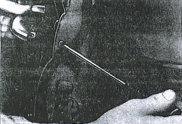
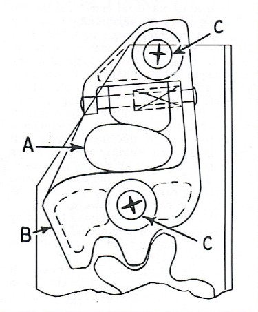
ADJUSTMENT
- Up or down adjustment will determine the actual point of engagement between the door lock rotor and the striker.
- If the door lifts as the dovetail (A), Figure 23, enters the door striker assembly, (B) the striker is too high and must be lowered.
- The in and out adjustment controls the tightness of the door against the body.
- The above adjustments can be made by loosening the two Phillips head screws (C) attaching the striker assembly to the pillar.
- After each adjustment, tighten the screws securely.
|
FIGURE 23
 |
Proper door alignment prolongs the life of the door locks, striker plates, check arms, and hinges and assures ease of door operation.
Check to see that the door properly contacts the weatherstrips at the door header weather strip, door opening weather strip and/or the door bottom weatherstrip.
Examine all weatherstrips to make sure they are firmly and evenly attached to doors and door openings.
- T raise or lower the door, place a jack as near the hinge as possible (this will hold the weight of the door as the hinge screws are loosened).
- Use an awl to scribe around the upper and lower hinges before loosening the hinge to front pillar screws, this will insure proper horizontal alignement after vertical adjustments have been made.
- Loosen the upper and lower hinge screws.
NOTE: The amount of vertical hinge movement is very limited. Do not damage the door with the jack when making this adjustment.
- Raise or lower the jack until the desired clearance is obtained, then tighten hinge screws securely. Check the scribe marks to ake certainthe rear section of the door did not move forward or rearward during the above operation.
- To move the uper section of the door ahead or back, loosen the upper hinge screws, to move the lower section, loosen the lower hinge screws and push or pull the door in the desired direction. Retighten hinge screws securely after adjustments.
|
FRONT DOOR - Complete, ALL Hudson Models 1948 thru 1954
REMOVAL
- Remove hinge pocket covers (D) and (E), Figure 24, on models so equipped.
- Drill out check arm rivet (F) using a 1/4" drill.
- Loosen the hinge screws at the door half of hinge and remove door.
NOTE: Have a helper hold the door in alignment while removing screws to prevent screws frm stripping.
INSTALLATION
- Install all hinge attaching screws and tighten slightly.
- Attach check arm to check arm bracket using check arm rivet. Peen rivet securely.
NOTE: Support bracket and check arm to prevent distorting the bracket of arm.
- Tighten door hinge screws securely and check door adjustment as outlined [above].
- Install hinge pocket covers (D) and (E) and fill hinge pockets above and below hinges with body caulking. Sealer must not project beyond edges of hinge pockets.
|
FIGURE 24
 |
NOTE: These hinge pockets can be installed on cars not so equipped EXCEPT [Jet models].
DOOR CHECK ARM - ALL Hudson Models 1948 thru 1954
REMOVAL
- Remove trim panel. See "Trim Panel Removal", [above].
- Drill out door check arm rivet, using a 1/4" drill.
- Push door check arm inward and remove through bottom opening in door inner panel.
INSTALLATION
Reverse procedure of removal. Using a new rivet, peen securely.
NOTE: If rubber bumper is deteriorated or spring is damaged, replace with a new assembly.
The door upper and lower weatherstrip are two separate pieces vulcanized to form a one piece weatherstrip. The weatherstrips are mounted on the doors and are cemented to the door inner panel. The lower (bottom) weatherstrips are also held in position with retainers bent over to hold the weatherstrip to the door panel.
REMOVAL
Bend down scalloped edges of retainer along the bottom of the door. Use a putty knife, break the seal between the weatherstrip and the door inner panel and remove weatherstrip.
INSTALLATION
- Remove all dirt and dried adhesive from door inner panel.
- Apply a thin coat of weather strip cement to the door inner panel and the weatherstrip; allow cement to become tacky before installing weatherstrip.
- Press weatherstrip firmly in place and bend up the bottom retainer.
NOTE: Make sure door drains slots are open and not covered by the weatherstrip or the bottom retainer. Do not close doors until cement has has sufficient time to dry.
The rear door weatherstrips are in two pieces. The rear door lower weatherstrip is held in position by retainers that have scalloped edges that are bent over the weatherstrips after the weatherstrips ahve been cemented to the door inner panel. The upper weatherstrip is cemented to the inner door panel.
REMOVAL
Bend down scalloped edges of retainer along the bottom of the door. Use a putty knife, break the seal between the weatherstrip and the door inner panel and remove weatherstrip.
INSTALLATION
- Remove all dirt and dried adhesive from door inner panel.
- Apply a thin coat of weatherstrip cement to the door inner panel and the weatherstrip; allow cement to dry until tacky and install weatherstrip.
- Press weatherstrip firmly in place and bend up the bottom retainer.
NOTE: Make sure door drain slots are open and not covered by the weatherstrip or the bottom retainer. Do not close doors until cement has had sufficient time to dry.
|
Do I have to take off the interior door panel to remove the exterior door handle?
No, removing the handle is quite simple. See "Outside Handle" instructions above for removal and installation. Why would someone want to remove just the handle? Perhaps they're treating their Hudson to some rechroming or a simple new coat of paint without doing a complete restoration.
Can you tell me where to get the felt-lined channels that surround the windows and how much I should get?
You can locate this item under the Replacement Parts List below. The measurements of the replacement kit offered in that list are a little long in order to allow trimming for a perfect fit, but for a Jetliner sedan with vent windows in all four doors: the run
channeling for front doors are 44" long, back doors are 53", belt lines are 18"
inner/outer for the front doors and 21" inner/outer for back doors. The div. bars
for all four doors are 32".
Door Weatherseal: K-gap #168
Window Channeling: Contact K-gap for this product. K-Gap actually receives this item from a business owned by a club member. For HET Club Members, you may contact the supplier by looking up Vic Z. under California in the Club Roster. Otherwise, please contact K-Gap. The Kit is $175.00 + shipping and Handling. Read through the Frequently Asked Questions area of this page, above, for measurements.
|
|
|
|
Courtesy HET JetSet - All Rights Reserved.
|
|