Hudson Jet |  |
DISCLAIMER: Unless otherwise noted, service information has been provided by an edition of the Mechanical Procedures Manual for Jet models. The data from the Manual includes information covering specifications, adjustments and detailed operation involved in maintenance and repair procedures. After market updates from Hudson Service Merchandisers and other sources have been added as well and are credited in italics. HudsonJet.net provides this reference as a courtesy and is not responsible for any work done using Hudson Motor Car Company's publications or other sources provided on this site. |
|
[U.S. Measure - ALL JET MODELS]
as suggested in Hudson Service Merchandiser
Vol. 5, No. 3, March 1953
- Gasoline Tank: 15 Gals.
- Cooling System:
- Without heater= 15 Qts.
- With Heater= 16 Qts.
- Engine Oil (Crankcase):
- Dry= 5½ Qts.
- Refill= 5 Qts.
- Transimission:
- Without Overdrive= 1½ Pts.
- With Overdrive= 2½ Pts.
- Rear Axle: 2½ Pts.
- Hydra-Matic Transmission Refill: 10 Qts.
Bore and Stroke: 3" x 4¾" Firing Order: 1-5-3-6-2-4
AMA HP 21.6 Displacement 202 Cu. In.
Valve Clearance: -Intake: .010" -Exhaust: .012"
Distributor Point Gap: .020" Spark Plug Gap: .032"
Spark Timing: Dead Center mark on Vibration Dampener |
Cylinder Compression.....................
Vacuum, Intake Manifold.................
Valve Tappet Clearance (Hot)..........
|
Minimum 100 lbs.
17-20" Hq.
Intake .010" - Exhaust .012"
|
Battery Specific Gravity..................
Starting Motor
Cranking Voltage.....................
Cranking Amperage.................
Stall Test:
Volts................................
Amperes..........................
Torque.............................
|
1.270
5.0 Volts
Approximately 160 Amps
2.0 Volts
Maximum Amps 280
Min. Ft. Lbs. 4.4
|
Coil Amperage Draw:
Engine Stopped.............................
Engine Idling..................................
|
5.0 Amps
1.5 - 2.0 Amps
|
Distributor:
Point Gap...............................
Cam Angle - (Dwell).................
Spring Tension........................
Condenser Capacity.................
Spark Advance:
|
.020"
39°
17 to 20 oz.
21-25 Mfd.
Automatic Vacuum
0° at 300 RPM 0° at 5-¼"
1° at 350 RPM 1° at 5-¾"
4.5° at 500 RPM 4° at 7-½"
12° at 1325 RPM 6° at 8-¾
13.5° at 1500 RPM 7.5° at 9-½"
|
Generator Output:
Cold - at 870 to 970 R.P.M..............
Cold - at 1925 to 2125 R.P.M..........
Hot - at 950 to 1050 R.P.M.............
Hot - at 2350 to 2550 R.P.M...........
|
6.4 Volts, 0 Amps
8.0 Volts, 45.0 Amps
6.4 Volts, 0 Amps
8.0 Volts, 45.0 Amps
|
Voltage Regulator:
Contact Point Gap...................
Contact Close.........................
Contact Open (After 15 Amp
Charge)...........................
Voltage Regulator Operates............
|
Minimum .015"
6.3 to 6.8 Volts
4.1 to 4.8 Volts
7.25 Volts 22 Amps at 100° F.
|
Spark Plug Gap.............................
Fuel Pump (Carter)
Pressure................................
Volume..................................
|
.032"
4 lbs. min. - 5 lbs. max. @ 1800 R.P.M.
1 quart 60 seconds @ 500 R.P.M.
|
Carburetor....................................
Float Setting..........................
Pump Travel...........................
Idle Adjustment......................
Climatic Control......................
|
Carter - Model WAI-2009S
1/2"
16/64"
1/2 to 1-½ turns open
Set one point lean
|
ENGINE TUNE-UP
Engine tune-up is important in maintaining engine performance, fuel economy, dependability, and complete owner satisfaction. Modern high speed engines demand accurate diagnosis and adjustments. it is recommended that the engine be tuned every 5,000 miles
The tune-up procedure taht follows is arranged in the usual order of performance, which is generally: compression, ignition, carburetion. Various manufacturers of testing equipment have set up specific procedures for their units which may be followed.
Many of the test involved in the tune-up are dependent upon a battery in good condition. If the battery is below standard it should be recharged, or replaced with a fully charged battery before the tune-up.
ENGINE
An engine taht fails to develop proper compression cannot be tuned. Compression should be checked with the engine at operating temperature with a reliable compression gauge. Test is made with ignition switch off and all plugs removed.
- Loosen spark plugs to break free any accumulated carbon.
- Use and air hose and blow out all dirt and carbon from spark plug cabities before removing plugs.
- Remove all plugs.
- Insert compression gauge in each spark plug hole in turn and crack engine with starter at least 4 compression strokes.
NOTE: Check reading on first and final stroke.
- Compression at each cylinder should be at least 100 pounds and should not vary more than 100 pounds.
NOTE: If compression gauge moves up in jerky steps of 10 or 20 pounds at a time, it generally indicates a sticking or leaking valve. If two adjacent cylinders show low compression reading, check for a leaking cylinder head gasket or loose cylinder head.
To differentiate between ring and valve lead, place a small quantity of oil on top of each piston and re-test. Oil will temorarily seal a ring lead and result in near normal compression. Little or no improvement will be noted if valve is leaking.
Correct any unsatisfactory condition found during the compression test before continuing with the tune-up.
| |
Upon satisfactory completion of the compression test, inspect, clean and adjsut spark plugs.
- Spark plugs with burned, blistered or cracked porcelains, or with pitted or burned electrodes, should be replaced with new plugs of the same type. For cast iron and aluminum cylinder heads, use Champion H-8 spark plugs. See "Electrical Section".
- Adjust spark plug gaps to .032" using a bending tool and wire loop gauge.
- Install new gaskets on the plugs and replace plugs in cylinder head. Tighten to 25 to 30 pounds with a torque wrench.
- Examine spark plug wires for loose terminals, cracked or broken insulation. Replace defective wires.
|
Figure 1
|
An engine in good condition will show a steady, or slight fluctuating, high vacuum reading from 18" to 21". Vacuum readings are affected by altitude. Over 2000 feet, the vacuum gauge will show about one inch lower for each 1000 feet of elevation.
- Remove wiper hose at intake manifold and connect vacuum gauge hose. (If the engine has a combination fuel and vacuum pump, disconnect the booster pump line at intake manifold.)
- Check carburetor and intake manifold nuts for tightness.
- Connect one lead of tachometer to the distributor primary terminal and the other lead to engine for ground. Adjust carburetor to obtain a smooth idle at 540 to 580 R.P.M. If car is equipped with Hydra-Matic Transmission, set idle speed at 490-510. Vacuum readings at sea level may be interpreted generally as follows:
18 - 21" Steady or with slight fluctuation: Engine in good condition.
15" Steady: Incorrect ignition timing.
10" Steady: Incorrect valve timing, or burned valves.
15 - 21" Fluctuating: Sticking valves or compression lead.
12 - 16" Drifting: Carburetor too rich or too lean.
Any number of engine conditions may cause the same action of the vacuum gauge. The exact cause must be established by process of elimination.
|
Check the valve tappets clearance when the engine is at normal operating temperature.
Correct valve clearances are .010" for intake valves, .012" for exhaust valves.
|
TAPPET ADJUSTMENT
- Raise front of car, place stand jack under frame cross member and remove right front wheel.
- Remove bolts on the fender side dust shield and attaching parts and take out shield from under the fender.
- Remove front and rear tappet covers and breather pipe. Take out the rear tappet cover by sliding cover forward and out.
- Adjust tappets and re-install parts.
|
The Cylinder Balance Tester compares the eveness of the power output of each cylinder in the engine.
- Connect the vacuum gauge in Figure 2 [at right] and set the throttle until engine is running at 1500 R.P.M.
- Ground the master clip of the cylinder balance tester and connect individual leads to the spark plugs 2-3-4 and 5. Engine will now run on 1 and 6.
- Note the reading on the vacuum gauge. Make the same test on each pair of cylinders in the following sequence. 6 Cylinders 1-6, 2-5, 3-4.
NOTE: A variation of more than 1 inch of vacuum or 40 R.P.M. between pairs of cylinders being tested indicates either a defective plug or unequal compression in a cylinder.
|
Figure 2
|
To isolate one weak cylinder, short out half the cylinders. The half giving the lower reading will include the weak cylinder.
Air bubbles prevalaent in the radiator filler neck (radiator filled with coolant to the overflow pipe) indicates a leaking cylinder head gasket, cylinder head or internal cracks in the water jackets.
An extreme blow-by at the oil filler pipe indicates defective piston rings. (Compression pressure by-passing the piston rings.)
|
Check the battery specific gravity with a hydrometer. A battery when fully charged should read 1.270 specific gravity at 70° F. A uniform hydrometer reading below 1.225 at 70° F. indicates a low battery that should be charged.
BATTERY LOAD TEST
Battery may be tested under load by connecting a voltmeter across the terminals and cranking the engine. Battery is satisfactory if it will crank the engine for ½ minute and the voltage does not drop below 4-½ volts. Slow cranking speed or lower voltage may be due to high resistance in the starter circuit. Check cables and retest. (DO NOT crank for more than ½ minute at a time.)
A standard cell tester may be used to make the load test. The cell tester has a shunt across the terminals which places each cell under load. Each cell should show 1-½ volts or over, and the variation between cells should not exceed .15 volts.
|
Figure 3
|
If a Starter-Battery Tester is not available, a voltmeter can be connected across the battery terminals while cranking the engine with the starting motor. The battery is in good condition if the starter cranks the engine at a good speed for ½ minute and the voltage does not fall below 4-½ volts. DO NOT crank for more than 30 seconds without allowing starter motor to cool.
NOTE: A slow cranking speed or voltage lower than 4-½ volts indicates a weak cell or high resistance in the connections to the starter. Check battery cables and connections and repeat the "Load Test".
|
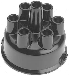
- Remove wires from cap and inspect cap and rotor for cracks and burned or corroded contacts. Replace defective parts.
- Clean spark plug cable sockets with tool No. KMO-230.
|
 |
CONTACT POINTS
- Inspect distributor contact points for alignment, corrosion, burning or pitting and clean with carbon tetrachloride.
- Replace burned or corroded points. If points are badly pitted, check condenser for over or under capacity.
- With a feeler guage set the point for the proper gap. Corrrect gap is .020".
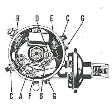
NOTE: Contact points adjustment is made by loosening the clamp screw (B) Figure 4 [at right], holding the stationary contact plate, theen turning eccentric adjusting screw (D) to move the contact point. Tighten clamp screw when correct gap is secured.
- Bend stationary contact point if necessary to secure correct alignment.
|
Figure 4
|
BREAKER ARM SPRING TENSION
- Hood a spring scale to the breaker arm at the contact and pull at right angles to the contact surfaces. Tension should be 17 to 20 ounces just as the points open.
- Adjust spring sension by loosening screw attaching breaker arm spring to plate and move end of springin or out of clip as necessary.
|
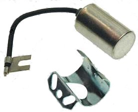
- Inspect condenser lead to see that it is not frayed or broken and is connected securely to breaker arm clip. Condenser mounting screw must make tight ground to breaker plate. Ground wire from breaker plate to subplate must be securely connected..
- Check condenser with suitable equipment and if capacity is not within range of .20 to .25 MFD, replace with new part.
|  |
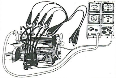
DISTRIBUTOR DWELL TEST
Check distributor cam angle or dwell on a distributor tester to determine the cam angle or degrees of dwell of the distributor point. This should be 39 degrees with distributor contact point set at .020".
If the dwell angle is too great, the contact point gap is set too close. If the dwell angle is too small, the contact gap is too wide. An erratic reading of the Dwell Meter will indicate faulty contact, a faulty breaker plate, a worn distributor shaft and bearings. A change of dwell angle when accelerating or de-accelerating, the engine will indicate a faulty breaker plate, bearing or support plate.
VACUUM ADVANCE ADJUSTMENT
Vacuum should be checked on a distributor tester that has a controlled source of vacuum and a vacuum gauge.
If the vacuum advance range does not conform with specifications, it may be varied by inserting or removing washers under the spring in the vacuum chamber. Carefully check for leaky diaphragm and sticking linkage.
AUTOMATIC ADVANCE
Place distributor on tester and check the advance curve R.P.M.'s against the degree of advance.
If the degree of advance is more than specifications call for at the same R.P.M., it indicates that the governor spring tension is too weak and the advance is too rapid.
If the degree of advance is less than specifications, call for at the same R.P.M., the spring tension is too stiff and the advance is too slow.
In most cases, the tension of the spring may be increased ro decreased by bending the brackets on the weight plates to which the springs are atttached, in order to make the springs conform to specifications.
Check the advance both up and down the speed range so that the sluggish action of the governor will be indicated and may be corrected by cleaning and lubrication.
NOTE: Every 2.000 miles, lubricate contact arm pivot, wick top of shaft, cam lobes and 3 to 5 drops of medium engine oil at oiler.
|
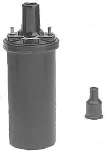
If a faulty coil is suspected, the coil should be tested with a test light or approved coil testing dquipment.
A quick test with the coil on the car can be made by removing the high-tension wire from the center of distributor cap and hold end of wire ¼" from cylinder head and while cranking engine, if a spark occurs regularly the coil can be considered satisfactory.
|
 |
IGNITION TIMING
- Place a chalk mark on the long line before No. 1-U.D.C. on the vibration dampener, Figure 5 [at right].
- Connect one lead of the power timing light to No.1 spark plug and the other lead to the negative terminal of the battery.
- With the engine idling properly, the timing light flash should occure when the chalk mark is in line with the pointer on the timing chain cover.
If timing is off, make the necessary correction by loosening the distributor advance arms crew (on octane selector) and rotate distributor clockwise for retard and counter-clockwise for advance. |
|
- Increase engine speed. The vacuum advance should be at full retard position but should advance readily when the engine speed is increased.
To set the timing without a timing light, remove No.1 spark plug and crank engine til No.1 piston starts up on compression stroke. Continue cranking until long line on dampener lines up with pointer. Loosen distributor quadrant screw and rotate distributor clockwise to the limit of the slot in the quadrant. Remove secondary wire from center of distributor cap and hold bare end of wire about 1/8" from the cylinder head. With ignition switch on, slowly rotate the distributor counter-clockwise just until a spark jumps from the wire to the cylinder head; then tighten quadrant screw.
Spark setting may be advanced with fuels of high octane rating.
Correct ignition timing is indicated by a slight "ping" at about 15 M.P.H. when accelerating at full throttle from 10 M.P.H. in high gear. If no "ping" is heard, timing should be advanced one quadrant graduation mark at a time until the "ping" is heard. |
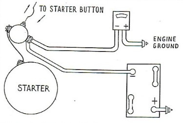
- Connect the negative voltmeter lead to the starter switch terminal (where the battery to starter cable is connected), Figure 6 [at right].
- Connect the positive voltmeter lead to engine for a ground.
- With the ignition key off, engage the starter motor and note the reading on the voltmeter. The cranking voltage should read 5 volts or more.
CAUTION: Crank engine intermittently (not more than 30 seconds) to prevent starter motor from overheating.
- If the voltmeter reading is less than 5 volts, check the battery and engine ground cables, starter cable and the starter solenoid to determine the low reading.
|
Figure 6
|
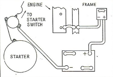
BATTERY AND ENGINE GROUND STRAPS
- Connect the voltmeter positive lead to the battery ground terminal, Figure 7 [at right].
- Connect the voltmeter negative lead to engine ground and a jumper to the frame.
- With ignition off, crank engine and make voltmeter reading, (should not be more than .2).
- If more than .2, check ground strap connections from battery to engine. Replace defective ground straps.
|
Figure 7
|
STARTER CABLE
- Connect the POSITIVE voltmeter lead to the "BAT" terminal of the starter and the negative lead to negative battery post.
- Crank engine again (ignition off). If the voltmeter reading is more than .2, check for loose connections or frayed cables.
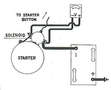
- Connect negative voltmeter lead to "BAT" terminal of starter solenoid switch and positive lead to motor terminal of the solenoid switch, Figure 8 [at right].
- Close the solenoid electrically to crank the engine; and if the reading is more than .2 volts, replace solenoid switch.
|
Figure 8
|
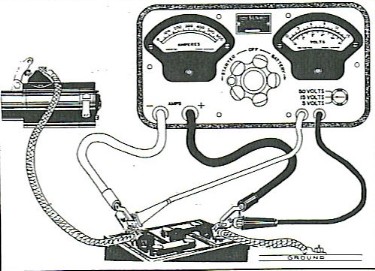
AMPERAGE DRAW TEST
- Turn battery starter test know to "off" position and the voltmeter "selector switch" to the 15 volt position and connect test leads, Figure 9 [at right].
- Press starter switch and crank engine for approximately 15 seconds and note the "exact" reading on voltmeter.
- Release Starter Switch and turn Starter Battery Tester knob clockwise until the voltmeter reads "exactly" the same as when cranking the engine. Ammeter reading should be 140 to 160 amperes (engine warm).
- Turn tester to off position after completing test.
|
Figure 9
|
NOTE: Excessively high readings indicate a short in the starting motor circuit or an excessive drag on the motor due to a bent armature shaft or the field coils touching the armature. Low readings indicate excessive resistance in the circuit caused by loose connections, worn brushes, or weak brush spring tension.
|
[In original manual, however, italicized portion is an additional excerpt as suggested in Hudson Service Merchandiser Vol. 5, No. 4, April 1953.]
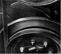
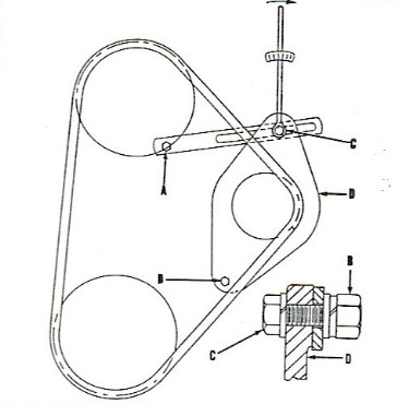
Due to the design, it is desirable to adjust the fan belt tension on the [Jet] Engines with a torque wrench. Although there is outlined in the Owner's Manual for these cars a procedure that will enable an owner to adjust the belt, for long life and minimum wear on water pump bearings, the following procedure is recommended.
- Loosen generator adjusting bracket bolt (A-Figure 10, at right), nut (B) and 2 generator support bracket bolts (D) three to four turns.
- Apply a torque wrench approximately 12" long and as nearly vertical as possible to the head of generator adjusting bracket bolt (C) and pull generator against fan belt.
- With torque wrench indicating 10-1/2 ft. lbs. tighten generator adjusting nut (B) securely. Remove torque wrench and tighten remaining 3 bolts securely.
|
Figure 10
|
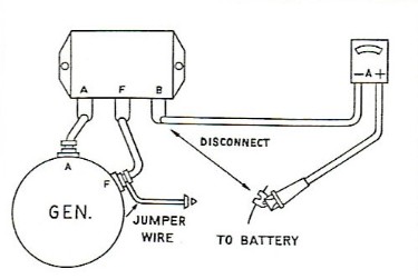
GENERATOR OUTPUT CHECK
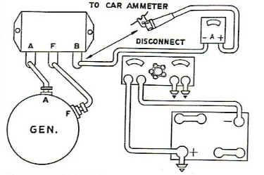
- Disconnect battery lead at voltage regulator "B" terminal; connect the ammeter negative lead to the regulator "B" terminal and the positive lead to the wire disconnected from the regulator, Figure 11 [at right].
- Install a jumper from generator field terminal to a ground. Momentarily raise the engine to about 1250 R.P.M. the reading on the ammeter should read 45 amperes minimum output.
|
Figure 11
|
CAUTION: The engine MUST NOT be run for more than a few seconds while making the above test, due to danger of burning out the generator. All lights and accessories must be turned off also to prevent damage due to excessive voltage.
NOTE: All generator tests should be made with the generator circuit at normal operating temperature.
|
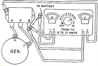
GENERATOR CIRCUIT RESISTANCE CHECK
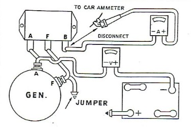
- Disconnect battery lead at voltage regulator "B" terminal; connect the ammeter negative lead to the regulator "B" terminal and the positive lead to the wire disconnected from the regulator, Figure 12 [at right].
- Install the negative voltmeter lead to the generator "A" terminal and the positive voltmeter lead to the battery negative terminal.
- Connect a jumper between the generator "F" terminal and a ground.
- Run the engine at a speed to deliver 20 amperes. The voltmeter should not read more or less than 8 (tenths) of a volt.
|
Figure 12
|
- If the resistance is more than .8, make the following checks with the ammeter connected as in paragraph 1.
- Remove the positive voltmeter lead from the battery and install to the "A" terminal at the voltage regulator. Ammeter should show less than .1 (tenth).
- Connect the voltmeter negative lead to the regulator "A" terminal and the voltmeter positive lead to the regulator "B" terminal. Ammeter should not show more than .3 (tenths).
- Next, connect the voltmeter positive lead to the battery negative terminal, negative lead to "B" terminal on regulator. Ammeter should not show more than .5 (tenths).
- Connect the voltmeter positive leads to engine ground, negative wire to base of regulator. Ammeter should show .2 (tenths) or less.
|
CIRCUIT BREAKER CHECK
To determine whether the circuit breaker points are closing at the proper generatr voltage and also whether they will open upon deceleration by amperage from the battery proceed as follows:
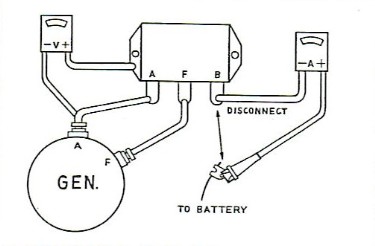
- Disconnect the battery wire at the voltage regulator "B" terminal and connect the ammeter between the voltage regulator "B" terminal and the wire disconnected, Figure 13 [at right].
- Connect voltmeter positive lead to base of regulator and negative voltmeter to the generator "A" terminal.
- Set carburetor adjusting screw so engine will idle at approximately 400 R.P.M.
|
Figure 13
|
- Increase engine R.P.M. by carefully rotating the accelerator bellcrank while watching he voltmeter.
NOTE: When the voltmeter reads at any point between 6.3 to 6.8 volts the circuit breaker points should close and the ammeter will show the generator is charging. When the circuit breaker points close, a slight drop back of the voltmeter needle will be noticed. In the event the drop back is not evident, slightly discharge the battery and recheck.
- Next, slowly reduce engine speed and watch the ammeter.
NOTE: When the ammeter reads 4 to 6 amperes, negative side of zero, the circuit breaker should open and the ammeter needle will return to zero. Perform operation 4 and 5 several times until you are sure your readings are correct.
- Proper adjustments can be made by bending the spring hanger on the circuit breaker. increasing the tension raises the opening voltage; decreasing the tension lowers the opening voltage. Contact gap must not be less than .015".
|
- Disconnect the battery wire at the voltage regulator "B" terminal and connect the test ammeter between the voltage regulator "B" terminal and the wire disconnected, Figure 14 [at right].
- Connect the voltmeter positive lead to the regulator base and the negative lead to the regulator "B" terminal.
- Run engine at approximately 2,000 R.P.M.
- Vary resistance until ammeter reads 19 amperes and then check the voltmeter reading which should be 7.25 volts. (Hot, cover in place.)
|
Figure 14
|
NOTE: If the car is out of warranty the voltage regulator can be set by bending the spring hanger to get this necessary reading. The unit must be final-checked with the voltage regulator cover in place as generally it will change the reading from .1 to .2 of a volt and must be compensated for in making this adjustment.- Stop engine, disconnect battery negative terminal and then proceed to remove the tester leaks from the voltage regulator and install the wires back on the "B" terminal of the regulator.
- Install voltage regulator cover.
VOLTAGE REGULATOR ADJUSTMENT
- Remove cover and change the armature spring tension by bending the lower spring hanger. Increasing the tension raises the operating voltage; decreasing the tension lowers it.
- Replace cover and recheck.
- After each adjustment, stop the engine and restart. Bring up engine speed to deliever 15 amperes before taking a reading.
|
CURRENT REGULATOR CHECK
- Disconnect the battery wire terminal "B" and connect the test ammeter between the voltage regulator "B" terminal and the wire disconnected, Figure 15 [at right].
- Connect a Starter-Battery Tester directly across the battery and set load to 45 amperes or use the equivalent in sealed beam lamps.
- Run engine to approximately 2,000 R.P.M. amperage reading should be 36 amperes. If it is not within a tolerance of one or two amperes of this reading, the unit should be taken to an autorized Auto-Lite dealer for replacement.
|
Figure 15
|
NOTE: If car is out of warranty, remove the voltage cover and adjust the current regulator spring hanger to the necessary 36 ampere output. To prevent operation of the voltage regulator unit place a jumper across voltage regulator points during this test. For final test always replace the cover on the unit.
CAUTION: Momentarily touch the negative battery cable to the battery negative post to determine that there is no spark between the battrey negative post and cable terminal then connect negative cable.
CURRENT REGULATOR ADJSUTMENT
- Remove cover and change armature spring tension by bending the lower spring hanger. Increasing the tension raises the operating amperage, decreasing the tension lowers it.
- Replace cover and recheck. Stop and start engine after each adjustment. Take readings with cover in place.
|
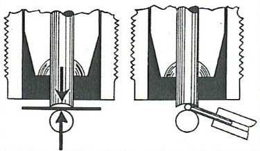
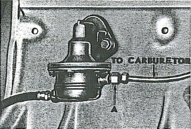
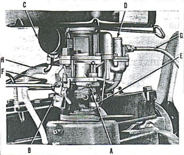
FUEL PUMP TEST
To determine if the fuel pump is operating properly, make the following tests:
- Be sure fuel lines are not blocked, leaking or have a stricture that would retard the flow of fuel to the pump. The flexible hose should be carefully checked for deterioration or cracks.
- Remove and clean sediment screen.
NOTE: If the combination fuel and vacuum pump is used, in addition, remove and clean the air filter screen located under the cover at the top of the pump. |
Figure 16
|
- Make sure all connections are tight after replacement.
- Disconnect the fuel line at the carburetor and connect the fuel pump gauge, Figure 16 [above].
- Start engine and run at 1800 R.P.M. Normal pressure should be 4 lbs. minimum to 5 lbs. maximum. Stop engine and watch pressure gauge. pressure should not fall perceptible after engine is stopped.
- If pressure falls; leaking pump valves are indicated.
- If pressure is below specifications, attach the vacuum gauge to the inlet port of the pump and operate the engine. Gauge should show a minimum of 6 inches of mercury for satisfactory operation.
VACUUM BOOSTER CHECK
To check the action of the vacuum portion of the combination fuel and vacuum pump, connect a vacuum gauge to the inlet port and disconnect outlet. Gauge should show 8-½" of mercury at 120 R.P.M.
Check the manifold heat control valve to see that spring is in good condition and valve is free. If damper shaft is stuck, remove the thermostat and spring, apply penetrating oil or kerosene and tap shaft for end play to break carbon or corrosion. The shaft should not be oiled. When properly freed, check springs and thermostat before installing and replace them if weak.
CLIMATIC CONTROL
- Remove the carburetor Climatic Control Cover. Check the heat control tube for leaks or obstruction and the choke valve and piston for free movement. Choke valve should open of its own weight when cover is removed.
- Reinstall the cover with graduations down and rotate counter clockwise to one point lean of center graduation.
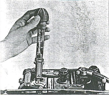
CARBURETOR INLET STRAINER
- Remove bowl cover strainer nut, gasket, and strainer screen. Clean screen and replace if corroded or damaged.
|
- Remove air cleaner, carburetor dust cover and screws attaching carburetor air horn.
- Disconnect throttle connector rod, bowl cover and check float level with gauge J-818-1 Figure 17 [at right]. Float level should be ½".
- To adjust, make sure needle is seated, raise flat and press down on float lever lip with a screw driver. Bend only a small amount at a time and do not disturb the curvature of the lip.
|
Figure 17
|
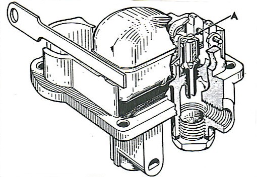
CARBURETOR FLOAT LEVEL UPDATE
as suggested in Hudson Service Merchandiser Vol. 5, No. 5, May 1953
Reports [were] received from the field that some Jet Engines may hesitate or cut-out when making a sharp turn. This condition can be corrected by raising the carburetor float level.
In such cases, it is recommended that the air cleaner, carburetor dust cover and bowl cover assemblies be removed and the float level checked and re-set, if it is found to be too low.
Raising or lowering the float level is by bending the lip of the float ("A" shown in illustration) which contacts the float needle, to reduce or increase the measurement between the soldered seam of the float and the projection on the float cover.
In this case, bend the lip "A" until the float level is raised from 1/2 to 7/16" of an inch. This results in raising the level of the fuel 1/16" and eliminates the condition of momentary starving on a sharp turn.
A new throttle return spring for Single Carburetor, [Jet Models], Part 309562, [was] released. This new spring raises the accelerator pressure approximately 50 per cent.
- With throttle valve seated and connector link in lower hole (short stroke) pump travel should be 16/64". Use Carter Pump stroke gauge T-109-117-S if available.
- Adjust pump travel by bending throttle connecting link at lower angle.
|
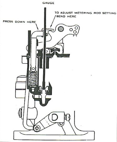
NOTE: The correct setting of metering rod is important and must be made after pump adjustment or when leaner than standard rods are installed.
- With air cleaner and dust cover off, remove hairpin clip and disconnect spring from metering rod, remove metering rod and disc.
- Insert metering rod gauge, J-1265 (Carter No. T-109-102). Hold gauge vertical and be sure gauge is seated in metering rod jet, Figure 18 [at right].
- Press down on vacuum piston link directly over piston until it contacts the pump arm. Clearance between metering rod pin and shoulder of gauge should be less than .005" with throttle valve seated. Gauge must not drag on pin.
- Adjust by bending lip on piston link at (A).
- Remove gauge and install metering rod and disc and connect metering rod spring.
|
Figure 18
|
as suggested in Hudson Service Merchandiser Vol. 6, No. 2, February 1954
The gasoline economy, smoothness, and general performance of care which are regularly operated at altitudes of 4,000 feet or more, can often be improved by slightly changing the carburetor calibration and ignition timing.
When the operation of the car at higher altitudes indicates the need for a leaner fuel mixture, it is recommended that the carburetor metering rod or rods be changed to one of the leaner types, depending upon the altitude in which the car is driven.
- Use standard metering rods from sea level to 4,000 feet.
- Use one size lean metering rods from 4,000 to 8,000 feet.
- Use two sizes lean metering rods from 8,000 to 12,000 feet.
- Use three sizes lean metering rods at altitudes of 12,000 feet and higher.
The use of leaner metering rods at altitudes lower than 4,000 feet may cause unsatisfactory engine performance and little, if any improvement in fuel economy. The standard and leaner metering rods used on the 1953 "C" Series and the 1954 "D" Series Hudson Models are as follows.
CAR
MODEL
1C & 2C Single
1C, 2C, 1D, 2D, & 3D Single
1C, 2C, 1D, 2D, & 3D Twin
4C & 4D Single
5C & 7C Single
5D & 7D Single
5C Twin
5D Twin
7C Twin
7D Twin |
CARB.
NO.
*2009S
2009SA
2013S
749S
776S
2115S
990S
2114S
968S
2113S |
STAN-
DARD
75-864
75-914
75-878
75-704
75-754
75-732
75-851
75-956
75-834
75-955 |
ONE SIZE
LEAN
75-907
75-920
75-904
75-712
75-732
75-980
75-856
75-977
75-861
75-974 |
TWO SIZES LEAN
75-908
75-921
75-905
75-713
75-741
75-741
75-857
75-978
75-862
75-975 |
THREE SIZES LEAN
75-909
75-922
75-906
75-714
75-742
75-981
75-858
75-979
75-863
75-976 |
*If carburetor is equipped with 75-914 metering rod, use leaner metering rods specified for 2009SA carburetor.
The Part numbers of the carburetors and metering rods shown above are those of the Carter Carburetor Corporation from whose service outlets they may be obtained.
Standard ignition timing is top dead center for cars with standard metering rods. However, when leaner then standard metering rods are installed, the ignition may be advanced up to 4 degrees (flywheel) before top center as the car is being operated at the maximum altitude specified for the particular metering rods.
|
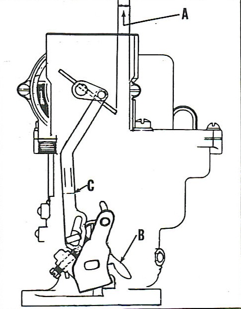
NOTE: Carburetor must be removed from engine.
- Crack throttle valve .020" by placing gauge J-1633 (Carter No. T-109-29) between throttle valve and bore of carburetor on side opposite the idle port, Figure 19 [at right].
- Clearance between percolator rocker arm lip and pump arm should be .005" to .015".
- Adjust by bending the rocker arm, using Bending Tool J-1389 to make this adjustment.
|
Figure 19
|
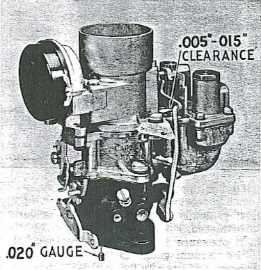
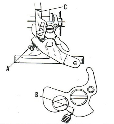
- With fast idle cam in normal idle position, tighten throttle lever adjusting screw (A), Figure 20 [at right], until it just seats against the cam.
- Hold throttle lever closed and pull cam back until low step is against but not on set screw (B), Figure 20.
- Clearance between lower edge of choke valve and air horn should be 5/8" as shown at (A), Figure 21 [below, right].
- Adjust by bending fast idle link at offset.
|
Figure 20
|
- Open throttle wide and check clearance between lower edge of choke valve and air horn. Clearance should be 7/16" (A), Figure 21 [at right].
- Adjust by bending cam (B) on throttle lever.
|
Figure 21
|
- Start engine and allow to warm up.
- See that choke valve is wide open.
- Set idle adjustment screw (A), Figure 22 [at right], ½ to 1-½ turns open to obtain smooth idle. Cars equipped with Hydra-Matic; set idle at 490 - 510 R.P.M., 540 to 560 for standard transmission and 575 for overdrive.
|
Figure 22
|
Coming soon......
Coil: Autolite CR-6012A, NAPA 1C7, Filco UC102, GP GC200, GP GC88, VallyForge GC40X, Hagens Auto Parts #E5
Distributor Cap: NAPA AL106, BorgWarner C143, Standard A1138, Autolite AIT-33, Hagens Auto Parts #C143
Generator: Auto-Lite GGW-4802S
Ignition Switch: 956-4704 (CHH) - Bailey Motors 800-394-8134
Rotor: NAPA AL112, BorgWarner D133, Surekit D133, Prestolite 4-2 (IAT-1016a), Hagens Auto Parts #D128
Spark Plugs: H10 Champion
Starters: Auto-Lite (w/hydra.trans) MZ-4172
Voltage Reg: (orig.type) #VBE-6104AIH, Autolite VBE-6101A
|
|
|
|
Courtesy HET JetSet - All Rights Reserved.
|
|