Hudson Jet |  |
DISCLAIMER: Unless otherwise noted, service information has been provided by an edition of the Mechanical Procedures Manual for Jet models. The data from the Manual includes information covering specifications, adjustments and detailed operation involved in maintenance and repair procedures. After market updates from Hudson Service Merchandisers and other sources have been added as well and are credited in italics. HudsonJet.net provides this reference as a courtesy and is not responsible for any work done using Hudson Motor Car Company's publications or other sources provided on this site. |
|
[Specs information also provided in Hudson Service Merchandiser
Vol. 5, No. 3, March 1953] |
Curb height (Front)
Curb height (Rear)
Caster
Camber
Maximum variation between right and
left wheel caster or camber
Toe-In measured at wheel rim
Pivot Pin Inclination
Wheel Bearing Type |
4-5/32"
6-1/16"
0° ± 1/2°
1/4° to 1-1/4° Positive
1/2°
0"-1/16"
3°28'
Adjustable Roller Bearing |
Wheel Bearing End Play
Tie Rod End Type
Tie Rod Adjustment
Steering Center Arm Pivot Nut
Outer Steering Arm Nut |
.001" to .003"
Plain Bearing
Threaded
(To increase - Turn counter clockwise)
(To decrease - Turn clockwise)
Torque 45-50 Ft. Lbs.
Torque 110 to 120 Ft. Lbs.
Tire Size: 5.90 x 15 - Air Pressure
6.40 x 15 - Air Pressure | Front Rear
24 24
24 22 |
|
|
CONSTRUCTION
Front suspension is the individual front wheel type with independent support arms and coil springs. This type of front wheel suspension permits either wheel to absorb road irregularities without effecting the other wheel.
Steering is from a center poin which permits smooth operation of the steering mechanism.
The supper support arm bushings (9), Figure 1, fit into the upper support arm bores and are threaded on to the ends of the pivot.
The assembly is attached to the frame side rails at the no. 2 crossmember by two bolts (7). Shims (10) between the upper support arm pivot and frame member provide caster and camber adjustments. At the outer end of the upper arma threaded pivot bolt (16) holds the spindle pivot upper support (17) to the arm.
The steering spindle pivot pin (46) is threaded into the upper suport pivot. The outer steering arm (53) is keyed to the steering spindle and the pivot pin. Below the steering arm a trunnion is mounted on the pivot pin. Steel threaded bushings (19) fit into bores in the outer end of the lower arm and onto the threaded portions of the lower support arm trunnion.
Steel bushings (5) are inserted through bores in the lower support arm at the inner end and onto the threaded ends of the inner (23) pivot. Two bolts (47) attach the pivot to the No. 2 crossmember.
The spring seat is riveted and welded to the lower support arm. At the lower end the coil spring (43) fits on the spring seat and the upper end into a recess in the frame at the No. 2 crossmember.
Two rubber bumpers are used on the front suspension, one on the upper arm (44) cushions and restricts downward movement of the upper support arm. The other on the lower support arm (51) restricts upward movement of the assembly.
|
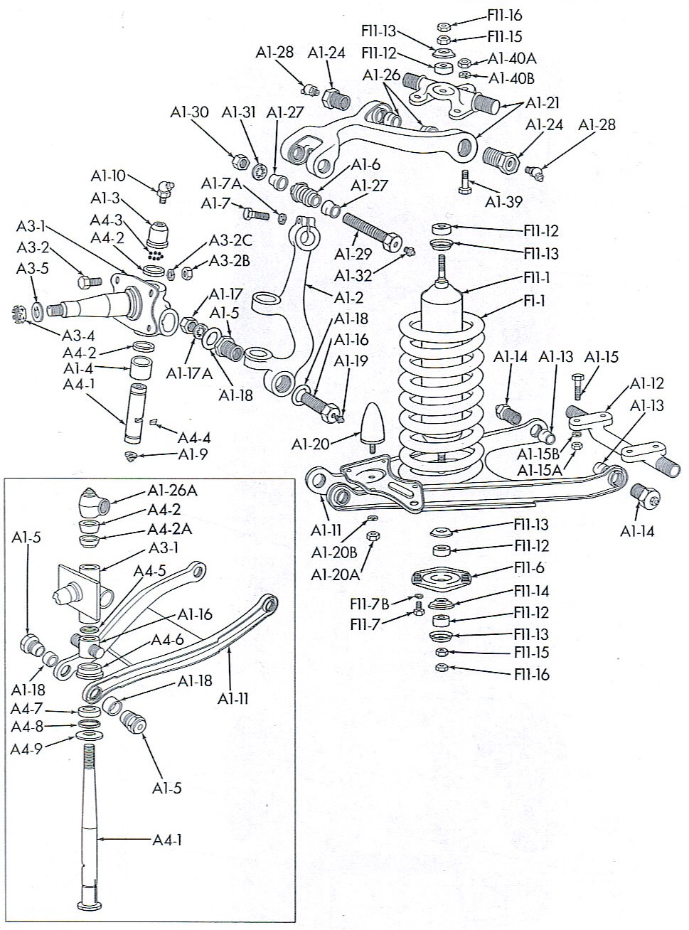
FIGURE 1
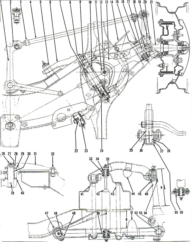 |
| LEGEND |
- Center steering arm
- Tie rod end
- Tie rod clamp
- Tie rod
- Bushing lower support arm inner
- Lower support arm
- Upper support pivot bolt
- Upper support arm bushing seal
- Upper support arm bushing rear
- Upper support arm shim
- Shock absorber retainer
- Shock absorber palnut
- Upper support arm assembly
- Steering spindle stop
- Upper support arm pivot bolt nut
- Upper support arm pivot bolt
- Upper support arm steering spindle pivot
- Grease fitting
- Bushing-lower support arm outer
- Steering spindle lower seal
- Steering spindle
- Lower support arm bushing-inner
- Lower support arm pivot
- Upper support arm pivot at frame
- Pivot pin grease lower seal
- Center steering arm pivot
- Center steering arm lock nut
- Center steering arm spacer lower
|
- Center Steering arm seal
- Needle bearing
- Center steering arm bracket
- Center steering arm to frame nut
- Shock absorber cup washer
- Shock absorber cushion
- Shock absorber retainer
- Dust cover seal
- Pivot pin dust cover seal retainer washer
- Pivot pin lower thrust bearing
- Center steering arm taper pin
- Center steering upper spacer
- Silencer
- Front shock absorber
- Coil spring
- Bumper upper support arm
- Steering spindle upper pivot seal retainer
- Steering spindle pivot pin
- Lower arm pivot pin
- Lower arm pivot to frame bolt
- Lower arm pivot to frame lock washer
- Lower arm pivot to frame nut
- Shock absorber anchor plate
- Bumper lower support arm
- Lower support arm trunnion bushing
- Outer steering arm
- Steering spindle pivot pin grease seal upper
- Dust cover seal
- Anchor plate bolt
|
|
REMOVAL (RIGHT OR LEFT)
- Raise car and place jack stands under inner ends of the lower support arms.
- Remove wheel and tire assembly and on left side remove fender side shield and battery.
- Remove shock absorber anchor plate botls, nuts and washers (56). Turn anchor plate 1/4 turn and push upward to clear spring seat.
- Disconnect stabilizer connector link from lower spring seat.
- Remove lower support arm pivot to frame bolts (47) nuts and lockwashers.
- Raise car allowing coil springs to expand and remove the spring.
NOTE: Coil springs are under extreme tension. Use care while removing coil springs to avoid damage or injury.
- Disconnect outer tie rod end from outer steering arm using tool J-2781.
- Remove four bolts from the brake backing plate and attach the backing plate under the fender with no strain on flexible brake hose.
- Remove upper support arm pivot to frame bolts, nuts and lockwashers, (7).
- Remove front suspension assembly. Wire shim packs (10) together and replace exactly as removed.
Installation is accomplished by reversing the rpeceeding operations. Check caster, camber and toe-in.
REMOVAL
- Jack up front end of car until wheels are clear of floor.
- Place jack stand under inner side of lower support arm
- Remove front and rear bushings (5) of the lower pivot (23).
- Remove the two bolts (47) from the lower support arm (6).
- Remove pivot (23) from the lower support arm
|
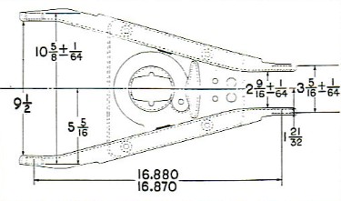
INSTALLATION
- Install the lower support arm pivot.
NOTE: Lower support arms are interchangeable for left or right side.
- Install lower support arm pivot to frame bolts.
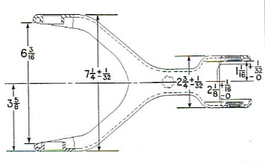
NOTE: Maintain the exact distance of 9-1/2" between the inner faces of the support arm while installing bushings. The arm must also be centered on the crossmember. The exact distance between the iner face of the support arm and the center line of the bolts holding the pivot to the crossmember should be 1-1/2". These distances must be maintained, Figure 2.
- Lower car to the floor and adjust camber, caster and toe-in.
|
FIGURE 2
 |
as suggested in Hudson Service Merchandiser
Vol. 5, No. 7, July 1953
To preclude the possibility of interference between the front tires and the stabilizer bar when making extreme right or left turns with the Jet Models, the steering stops have been redesigned.
This change involves the removal of the stops from the front brake backing plates and the installation of new stops on the rear upper flanges of the lower support arm assemblies. The new stops control the steering movement by contacting the outer steering arms while the earlier type stops which were welded to the brake backing plates, contacted the ends of the lower support arms. (See accompanying illustration.)

The advantages of the new steering stops are such that they should be installed on all 1C and 2C Models in stock as well as on owner's cars when they come into your Service Dept. for any reason. Secure your requirements from your Zone or Distributor by ordering Front Suspension Steering Stop, part number 309219 right and 309220 left.
Installation can easily be made in a few minutes since the stops are attached to the support arms by only one bolt on each side and the holes for the bolts are already drilled in the support arms flanges of all cars. It is not necessary to remove the old stops from the brake backing plates as the new ones limit the front wheel movement and those on the backing plates become ineffective.
REMOVAL
- Place jack under lower support arm near wheel and jack up front of car until front wheel is clear of the floor.
- Remove front fender shield.
- Remove wheel and tire assembly.
- Remove bolts (7) from the upper support arm pivot (24) to frame.
NOTE: The battery and battery carrier and fender side shield should be removed to make the left upper support arm pivot and bushing assembly accessible for removal.
- Remove the nut (15) and pivot pin upper support bolt (16) from the spindle pivot (17).
- Remove upper support arm (13) and pivot (24) assembly.
- Remove pivot bushings (9) and pivot (24) from suport arm.
|
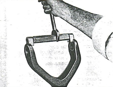
INSTALLATION
NOTE: The upper support arm pivot bushing (9) is self threading in the support arm. In assembling of the upper support arm pivot and bushing it is necessary to maintain a proper spread of the pressed steel support arm to insure correct tension on the threads of the pivot after the bushings have been installed.
- Install spreader tool (J-3957), Figure 3, with the slotted ends fitting against the inner face of the uppoer support arm. Turn the hex portion of the spreader tool until the outer surfaces of the support measure 7-1/4" apart. Install the pivot so it is centralized in the support arm.
|
FIGURE 3
 |
- Start the bushings on both ends of the pivot. Lubricate them with a tapping compound such as lard oil which will permit the bushings to cut their own threads in the support arm without scoring. Thread the bushings into the support arm and tighten to 110 foot pounds torque.
NOTE: The distance between the inner faces of the upper support arm is 6-3/16" as shown in Figure 4. The upper support arm assembly must be free to move from a horizontal position by its own weight plus a pressure no greater tahn 5 pounds applied to the arm. The pivot must not be rotated as this will throw the support arm off center with the pivot.
- Assemble the upper support arm and pivot to the frame and tighten attaching bolts to 60 to 70 foot pounds torque.
NOTE: Be certain that shim packs are installed exactly as removed. Omission or transposition of shims will alter camber and caster setting.
- Install spindle pivot upper support bolts (16) and tighten nut to 80 to 90 foot pounds torque.
- Mount tire and wheel assembly, battery and fender side shield if removed and lower car to the floor; check camber, caster and toe-in.
|
FIGURE 4
 |
REMOVAL
- Raise front wheels of car and place jack stands under the frame side rails behind the tie rod assemblies.
- Remove the wheel and hub and drum assembly.
- Remove the four bolts attaching the brake backing plate assembly to the steering spindle. Attach brake assembly to fender being careful to protect brake flexible hose.
- Remove the shock absorber anchor plate bolts (56), Figure 1. Pull spindle assembly outward slightly.
- Carefully lower jack until coil spring tension is relieved and remove spring.
- Back out spindle upper support (17) from threaded upper end of pivot pin (46).
- Remove cotter pin and nut from outer steering arm (53) and remove outer steering arm and key.
- Support the lower arm (6), and trunnion (18) assembly, tap the pivot pin (46) downward and remove.
NOTE: If the pivot pin sticks in the steering spindle bore, install the 3/4" - 11 support bolt nut on the pivot pin upper end. The pin can then be driven out of the steering spindle without damaging the pivot pin threads
- Remove the pivot pin upper grease seal (54), reatiner 945), lower grease seal (25), thrust ball bearing (38), dust cover (36), dust cover seal (55), and seal retainer washer (37).
INSTALLATION
- Install the lower grease seal retainer washer, grease seal and bearing, pivot pin grease seal and retainer.
NOTE: The thrust ball bearing should be a slip fit, having .005" to .015" pin to bearing clearance.
- Insert the pivot pin through the lower trunnion support and install the stering spindle on the pin.
NOTE: Align the machined groove in the pivot pin with the groove in the steering spindle outer steering arm bore.
- Install the Woodruff key in the outer steering arm inserting steering arm in spindle and install steering arm nut and cotter pin, tightening nut to 110-120 ft. lbs.
- Slip the upper pivot pin grease seal retainer and grease seal over the upper end of the pivot pin.
- Thread the upper pivot support onto the upper end of the pivot pin.
NOTE: The distance between the upper support edge and teh top of the steering spindle assembly should be 6-5/8", Figure 1.
- Install the coil spring in the upper spring recess and with a floor jack raise the lower support arm compressing the coil spring.
NOTE: Be sure silencer is in position.
- Rotate the pivot pin and steering spindle assembly inward at the top and guide the upper pivot into position at the outer end of the upper support arm. Thread the upper pivot support bolt through one side of the upper support arm and install the dust seal over the pivot support bolt. Thread the support bolt through the upper support pivot, through the other dust seal and through the opposite side of the arm. Install the support bolt nut and tighten to 80 to 90 foot pounds torque.
NOTE: The upper support pivot must be centered on the support bolt at the outer end of the upper support arm. There should be 3/16" between the inner face of the upper support arm and the end of the upper support pivot.
Install the tie rod to the outer steering arm and tighten the tie rod end nut to 60 to 70 foot pounds torque.
- Mount the brake backing plate on the steering spindle and tighten the four attaching bolt nuts to 30-35 foot pounds torque.
- Install wheel hub and drum and wheel and tire assembly.
- Lower the car to the floor and check caster, camber and toe-in.
REMOVAL
- Remove draglink at the front by backing off the adjusting plug and ball seat.
- Remove tie rod ends from the steering center arm using tool J-2781.
- Remove the three bolts attaching the center steering arm bracket 932) to the No. 2 crossmember.
- Remove the center pivot nut (27) and remove the center steering arm and pivot as an assembly.
|
INSTALLATION
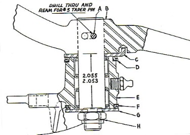
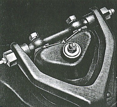
- When installing new bearings in the center steering arm bracket, space the bearings as shown in Figure 5. Apply pressure on the outer race on the end carrying the part number and manufacturers name.
- If necessary to replace the steering arm pivot shaft, the new shaft should be pressed in place maintaining the 2.053" to 2.055" dimension as shown before drilling the hole for the No. 5 taper pin (A).
- The steering arm seal consists of a steel washer to which synthetic rubber is bonded. A separate retainer is therefore not required.
- When installing the seals the rubber lips fit the casting grooves as shown in cross section, Fgiure 5, and the spacers (C) and (g) are isntalled as shown.The center steering arm pivot bolt nut (H) should be tightened to 50 to 60 foot pounds torque.
|
FIGURE 5
|
|
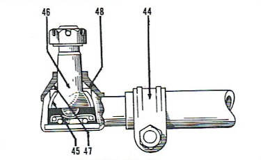
Tie rod ends are the self adjusting type. The ground steel bearings (45), Figure 6, is located between the stud (46) (which is prevented from losening ro rattling by the tension spring) and the tie rod end forgin. a curved steel dust cover (48) makes a tight metal seal, but to insure this being as nearly dust proof as posiible, a rubber seal (47) also seals the unit. |
FIGURE 6
|

REMOVAL
- Remove the cotter pins and nuts from both ends of the tie rod.
- Using tool J-2781, Figure 7, remove the tie rod ends.
- Using tool J-2781 remove the inner end.
|
FIGURE 7
|
INSTALLATION
New tie rod end installation and reassembly is accomplished by reversing procedure of removal and disassembly.
NOTE: When installing new tie rod ends threads the ends into the tie rod equally. Do not tighten clamps too tightly as the resulting distortion will destroy the clamping affect. Correct torque should be (20 to 30) foot pounds. Final toe-in adjustment must be checked with steering gear on high point, while tie rod adjustment is being made.
TURNING PULL
The amount of steering pull on the front wheels required to turn the wheels is measured in the following manner:
- Disconnect the drag link and place roller plates under the front wheels.
- Hook spring scale J-544-A over the tire tread in a horizontal plane with the wheel spindle center line.
NOTE: A pull no greater than 25 pounds should be required to turn the wheels on the roller plates. Greater pull required indicates binding of pivot pins, tie rod ends or a lack of proper lubrication.
GENERAL INSPECTION
Before checking the alignment of the front wheels, the following operations should be performed in the order listed. A successful alignment job cannot be accomplished unless these inspection operations are performed.
- Inflate all tires to recommended pressures.
- Check condition of tires (blowout patches, thin treads, vulcanizing, etc.).
- Wheel and tire run-out, wobble or eccentricity.
- Brakes for dragging condition.
- Wheel balance.
- Front wheel bearing adjustment.
- Front and rear riding heights.
- Pivot pin and bushing clearance.
- Upper and lower support arm bushings.
- Steering gear adjusting points.
- Shock absorber control.
- Rear springs and "U" bolts.
- Location of steering "high point".
- Divide total toe-in equally between the front wheels.
When checking front wheel alginment, the car must be level. It should be empty with no luggage or load in the trunk.
NOTE: Rock the car back and forth several times and allow it to settle.
Measure the distance from top of the lower support arm, the lower edge of the upper rebound jacket. This measurement should be 4-5/32" on each side (B), Figure 1, (Curb load - less passengers). If the two measurements vary more than 1/2", replace one or both of the coil springs as required.
There are two types of coil spring available for service, low rate and high rate. The springs can be identified by the part number stamped on the top of the coil spring.
|
RIDING HEIGHT - REAR
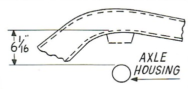
Front wheel alignment is affected by weak rear springs or shock absorbers. To determine the riding height measure the distance vertically from the top of the rear axle housing tube to the upper edge of the rear axle rubber bumper, Figure 8. The distance should be 6-1/16" (Curb load - less passengers).
|
FIGURE 8
 |
WHEEL BEARING ADJUSTMENT
- Jack up the car until the front wheels are clear of the floor.
- Remove the outer and inner wheel hub caps.
- Remove the cotter pin and tighten the nut until all bearing parts are in contact and a slight bind is felt when the wheel is rotated by hand.
- Back nut off one or two serrations until the wheel revolves freely.
- Install and clinch the cotter pin.
- Replace the inner and outer hub caps and lower the car to the floor.
Before proceeding to make a check of front wheel alignment, the steering gear must be on the "high point" and the tow-in must be divided equally between the front wheels.
Steering "hihg point" is the position of the steering worm and sector at their point of minimum clearance when the wheels are in a straight ahead position. The high point can be determined as follows:
- With the drag link disconnected from the pitman arm, grasp the pitman arm with the hand and move it forward and backward for a short distance along the center of the arc of travel of the arm; no movement should be felt.
- With the worm and sector on the high point, the steering wheel spokes should be in a horizontal position. If the spokes are not in this position, remove the horn button and check to see that the notch on the upper end of the worm shaft is straight down toward the floor.
To prolong tire life and assure easy car handling and maximum safety, it is essential that proper front end alignment be maintained.
Unintentionally striking the curb a severe blow when turning, parking, or skidding may not cause enough damage to make it visible to the eye, but will be reflected in the handling of the car at high speeds or in abnormal tire wear.
Front wheel alignment is the correct adjustment of five inter-related factors to provide easy steering and control of the car. The five factors are camber, caster, king pin inclination and toe-in and toe-out curves.
Camber is the amount of degrees that the front wheels incline away from a vertical place. With positive camber, the front wheels are farther apart at the top and closer together at the bottom. Negative camber is the reverse of the above, with the wheels closer together at the top and farther apart at the bottom. Camber is necessary to compensate for front spring deflection under load and road crown. Camber specifications is from 1/4° - 1-14° Positive with not more than 1/2° variation between wheels; above values with the equivalent of a 5 passenger load.
NOTE: Adjustment of the camber angle should not be attempted until caster and king pin inclination have been checked. A change in the camber adjustment will also change the pivot pin inclination.
|
ADJUSTMENT
Camber adjustment is provided by shims plaed between the upper control arm inner pivot and the No. 2 crossmember, Figure 9. Three thickness of shims are provided (1/32", 1/16" and 1/8"). When the caster has been determined to be within specified tolerances the same thickness of shims must be used at each pivot bolt. Adding shims will decrease positive camber setting and subtracting from the shim pack will increase positive camber. |
FIGURE 9
 |
Caster is the amount in degrees that the pivot pin is inclined away from a vertical plane, either toward the front or rear of the car. Positive caster is the inclination of the top of the pin toward the rear of the car, while negative caster is the tilting of the top of the pin toward the front of the car.
Caster assists in keeping the wheels in a straight ahead position. When turning a curve, the caster lever action helps return the wheels to a straight ahead position. The caster setting helps provide ease of steering and vehicle control. Caster specifications is 0° plus or minus 1/2° above values with the equivalent of a 5 passenger load. If car is emtpy, caster angle should be minus 1/2°.
ADJUSTMENT
The shim packs between the upper pivot and the No. 2 crossmember provides caster adjusment also. Altering the shim, thickness at either the forward or rear attaching bolt of the pivot changes the caster setting. By addingshims at the forward pivot bolt and removing shims at the rear pivot bolt, positive caster is decreased. Subtracting from the forward shim pack and adding to the rear shim pack moves the pivot pin toward the rear increasing positive caster.
Pivot Pin inclination is the outwar dtilt of the pin at the bottom. Its purpse is to reduce the need for excessive camber to put the center of the tire in contact with the road. Correct pivot pin inclination is 3°28'.
Camber is closely allied with pivot pin inclination and a change in camber setting also effects the pivot pin setting. An incorrect pivot pin angle indicates a bent pivot pin, frame, steering spindle or support arm. To correct this condition, the frame must be straightened or the damaged parts replaced.
Toe-in is the setting of the front wheels closer together at the front than at the rear, measured at the wheel rim. When the car is in forward motion, the front wheels assume parallel positions that minimize lateral tire scuffing.
ADJUSTMENT
Adjustable tie rods provide the means of obtaining correct toe-in setting. Adjustment should be made with the front wheels in a straight ahead position and the steering gear center on the high point.
STEERING GEOMETRY
Steering geometry or toe-out on curves is the mechanics of relative toe-out when the wheels are turned to the right or left. Toe-out is controlled by the movement of the tie-rods and the angularity of the outer steering arms.
When caster, camber, pivot pin inclination and toe-in are found within specifications, and toe-out on curves can be assumed to be correct. If there are indications of incorrect toe-out on curves, check for bent outer steering arms.
To check toe-out, place wheels on turn plates. The turning angles should be as follows:
|
| Left Turn | Right Turn |
| Left Wheel 30° Right Wheel 25° |
Left Wheel 30° Right Wheel 25° |
The variation between the right and left wheel angle should be no more than 30 minutes plus or minus.
|
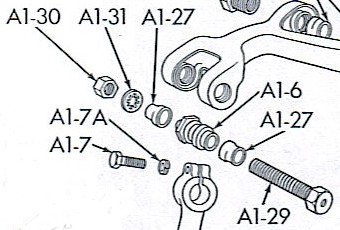
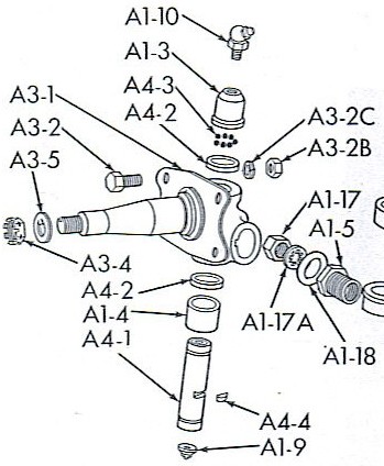
|
Typical Front Suspension - Exploded View
Group &
Illus. No. |
Original Part No. |
Front Suspension Part |
Per Car |
Picture |
|
|
|
|
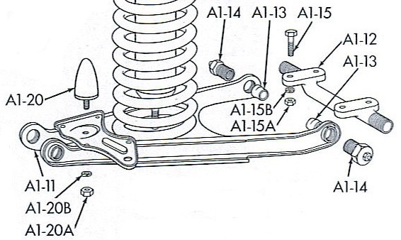 |
| A1-11 |
C 308203 |
Support Arm Assembly - Lower |
2 |
| A1-12 |
F 308206 |
Pivot - Lower Support Arm at Frame |
2 |
| A1-13 |
BX 165972 |
Seal - Lower Arm Pivot |
4 |
| A1-14 |
F 159739 |
Bushing - Lower Arm Pivot |
4 |
| A1-15 |
BX 171800 |
Bolt - Lower Arm Pivot to Frame |
4 |
| A1-15B |
BX 171817 |
L/Washer - Lower Arm Pivot to Frame Bolt |
4 |
|
|
|
|
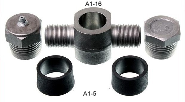
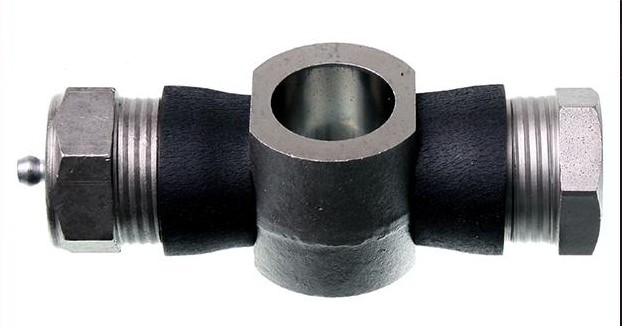
| A1-16 |
BX 308207 |
Trunnion Assembly - Lower Arm to Pivot Pin |
2 |
|
| A1-5 |
BX 308824 |
Bushing Assembly - Lower Arm Trunnion Rear |
2 |
| A1-5 |
BX 308712 |
Bushing - Lower Arm Trunnion Front |
2 |
| A1-18 |
BX 308210 |
Seal - Lower Arm Trunnion Bushing |
4 |
|
|
 |
|
|
|
|
|
| A1-20 |
F 308211 |
Bumper - Lower Support Arm (Rubber) |
2 |
|
F 308225 |
Bumper - Upper Support Arm (Rubber) |
2 |
| A1-20A |
BO 12481 |
Nut - Bumper Attaching |
4 |
| A1-20B |
BT 70414 |
L/Washer - Bumper Attaching |
4 |
|
|
|
|
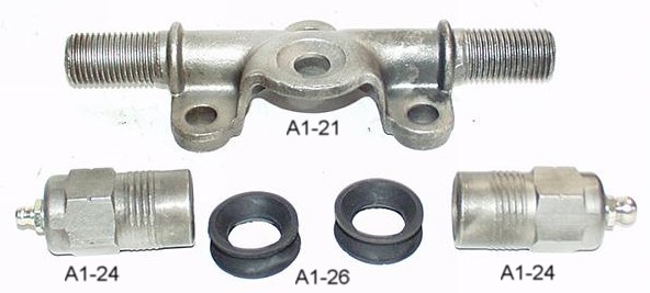
| A1-21 |
BX 308212 |
Support Arm & Pivot Assembly - RH - Upper |
1 |
|
| A1-21 |
BX 308213 |
Support Arm & Pivot Assembly - LH - Upper |
1 |
|
| A1-24 |
F 308218 |
Bushing - Pivot to Arm |
4 |
|
| A1-26 |
BX 308219 |
Seal - Pivot to Arm Bushing |
4 |
|
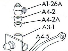
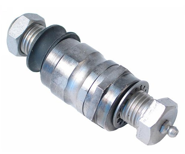
| A1-26A |
BX 308220 |
Support Assembly - Upper Arm to Pin |
2 |
|
|
F 45928 |
Grease Fitting - Upper Support Assembly |
2 |
| A1-29 |
BX 308223 |
Bolt - Support to Arm |
2 |
|
|
F 153497 |
Grease Fittiing - Upper Support Bolt |
2 |
|
BX 171912 |
L/Washer - Support to Arm Bolt |
2 |
| A1-30 |
BX 308224 |
Nut - Support to Arm Bolt |
2 |
| A1-27 |
BX 308299 |
Seal - Support to Arm bolt |
4 |
|
BZ 45353 |
Grease Fitting - Upper Arm Pivot Front Bushing |
2 |
|
F 45928 |
Grease Fitting - Upper Arm Pivot Rear Bushing |
2 |
|
BX 308226 |
Shim - Upper Arm Pivot to Frame Adjusting (1/32") |
AR |
|
BX 308227 |
Shim - Upper Arm Pivot to Frame Adjusting (1/16") |
AR |
|
BX 308228 |
Shim - Upper Arm Pivot to Frame Adjusting (1/8") |
AR |
|
BX 171799 |
Bolt - Upper Arm Pivot to Frame |
4 |
|
BM 170981 |
L/Washer - Upper Arm Pivot to Frame Bolt |
4 |
Group &
Illus. No. |
Original Part No. |
Steering Spindle Part |
Per Car |
Picture |
| A3-1 |
BX 308187 |
Spindle-RH |
1 |
 |
| A3-1 |
BX 308188 |
Spindle-LH |
1 |
| A3-2 |
BX 63 |
Bolt-Spindle to Backing Plate |
8 |
| A3-2 |
BX 12415 |
Nut-Spindle to Backing Plate Bolt |
8 |
| A3-2 |
BO 73 |
L/Washer-Spindle to Backing Plate Bolt |
8 |
| A3-4 |
F 71608 |
Nut-Spindle |
2 |
| A3-4 |
BZ 150572 |
Washer-Spindle |
2 |
|
F 308197 |
Washer Assembly-Grease |
2 |
Group &
Illus. No. |
Original Part No. |
Pivot Pin Part |
Per Car |
| A4-1 |
F 308189 |
Pin-Spindle Pivot |
2 |
| A4-2 |
BX 308195 |
Seal-Pivot Pin Upper Oil |
2 |
| A4-2A |
BX 308196 |
Retainer-Pivot Pin Upper Oil Seal |
2 |
| A4-4 |
BM 71154 |
Key-Pivot Pin |
2 |
|
|
|
|
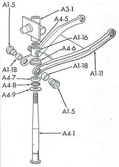 |
| A4-5 |
BX 308190 |
Seal-Lower Oil |
2 |
| A4-6 |
BX 308192 |
Cover-Lower Dust |
2 |
| A4-7 |
F 308191 |
Bearing-Pivot Pin Thrust |
2 |
| A4-8 |
BX 308193 |
Seal-Lower Dust Cover |
2 |
| A4-9 |
BX 308194 |
Washer-Dust Cover Seal Retaining |
2 |
|
|
|
|
Group &
Illus. No. |
Original Part No. |
Steering Arms |
Per Car |
Picture |
|
BX 308231 |
Arm-RH-Outer Steering |
1 |
|
|
BX 308232 |
Arm-LH-Outer Steering |
1 |
|
|
BX 171801 |
Nut-Outer Steering Arm |
2 |
|
|
BX 171802 |
Washer-Outer Steering Arm |
2 |
|
|
BX 308234 |
Arm and Pivot Assembly-Center Stering-LHD |
1 |
|
|
BX 308915 |
Arm and Pivot Assembly-Center Stering-RHD |
1 |
|
|
BX 300336 |
Pivot-Center Steering Arm |
1 |
|
|
BX 170998 |
Taper Pin-Center Steering Arm to Pivot |
1 |
|
|
BX 300596 |
Spacer-Center Steering Arm Pivot Upper |
1 |
|
|
BX 300337 |
Spacer-Center Steering Arm Pivot Lower |
1 |
|
|
BX 171262 |
Locknut-Center Steering Arm Pivot |
1 |
|
|
F 308079 |
Repair Kit-Center Steering Arm (includes seals) |
1 |
|
|
BX 308236 |
Bracket and Bearing Assembly-Center Steering Support |
1 |
|
|
BX 170996 |
Needle Bearing-Center Steering Arm Pivot |
2 |
|
|
BZ 45353 |
Grease Fitting-Center Steering Arm |
1 |
|
|
BZ 302553 |
Seal-Center Steering Arm Support Bracket Bearing |
2 |
|
|
BX 170337 |
Bolt-Pivot Support Bracket to Frame |
3 |
|
|
BZ 71445 |
L/Washer-Pivot Support Bracket to Frame Bolt |
3 |
|
|
BX 171455 |
Nut-Center Arm Bracket to Frame Bolt |
3 |
|
Group &
Illus. No. |
Original Part No. |
Tie Rod |
Per Car |
Picture |
|
C 308238 |
Tie Rod Assembly |
2 |
|
|
C 307933 |
Tie Rod |
2 |
|
|
BX 153500 |
Clamp |
4 |
|
|
BX 70361 |
Bolt-Clamp |
4 |
|
|
BO 12481 |
Nut-Bolt Clamp |
4 |
|
|
BT 70414 |
L/Washer-Clamp Bolt |
4 |
|
|
BX 71156 |
Nut-End Stud |
4 |
|
|
F 153497 |
Grease Fitting-End Cover |
4 |
|
|
F 307934 |
Kit-Ends Complete-Service |
1 |
|
|
F 307935 |
End Assembly-RH Thread-Service |
2 |
|
|
F 307936 |
End Assembly-LH Thread-Service |
2 |
|
Group &
Illus. No. |
Original Part No. |
Front Stabilizer |
Per Car |
Picture |
|
C 308660 |
Bar Assembly-Torsion |
1 |
|
|
BZ 300667 |
Bushing-Rubber |
2 |
|
|
BZ 308663 |
Bracket-Torsion Bar Bushing |
2 |
|
|
BZ 308698 |
Spacer-Torsion Bar Bushing |
2 |
|
|
BM 171096 |
Washer-Torsion Bar Bushing Spacer |
4 |
|
|
BO 18236 |
Bolt-Torsion Bar Bushing |
4 |
|
|
BZ 104 |
L/Washer-Bracket Bolt |
4 |
|
|
BZ 300589 |
Connector-Front Stabilizer |
2 |
|
|
F 300590 |
Cushion-Connector |
8 |
|
|
ZF 46718 |
Retainer-Connector Cushion |
8 |
|
|
ZF 47605 |
Cup Washer-Connector Cushion |
8 |
|
|
ZF 46720 |
Nut-Connector |
4 |
|
|
MF 170105 |
Locknut-Connector |
4 |
|
Center Pivot Steering Kit - H675 - Clifford's 909-734-3310
Swaybar Link Pins and Bushing Kits: MOOG #K5254 (8 Inch Pins, 7 1/2 Inch Pins Available)
Tie-Rod Ends: NAPA/Allied - 5191L / 5191R
Upper Knuckle Support Pin Assembly: McQuay-Norris #FA-194, Rare Parts (800) 621-2005 (#MNFA194), PT# RP16986 (16986-2H52), Just Suspension at (973) 808-0066
Upper Inner Control Arm Shafts: MOOG #K35
Trunnions: These can be reclaimed, depending on whether the one you have is hardened or not. Some are, some aren't. If you have one that a hacksaw will cut, then you cut a longitudinal slit along the length of the threaded portion, then in large vice compress the threads inwards until it is a tight fit on the bolt. Grind a V along the cut, not too deep that you are interfering with the threads, and carefully arc weld right along. This shrinks the thread down to fit the bolt. Geoff Clark of New Zealand has done this to both sides of his Jet, successfully. Or, give Gary of Illinois a call at 262-662-9595 I know they were doing inventory on a bunch of Jet parts a while back. Also, try RareParts.com (800-621-2005) and ask for 16985 (lower) and 16986 (upper).
|
|
|
|
Courtesy HET JetSet - All Rights Reserved.
|
|