Hudson Jet |  |
DISCLAIMER: Unless otherwise noted, service information has been provided by an edition of the Mechanical Procedures Manual or Hudson Owner Manual for Jet models. The data from the Manuals includes information covering specifications, adjustments and detailed operation involved in maintenance and repair procedures. After market updates from Hudson Service Merchandisers and other sources have been added as well and are credited in italics. HudsonJet.net provides this reference as a courtesy and is not responsible for any work done using Hudson Motor Car Company's publications or other sources provided on this site. |
|
|
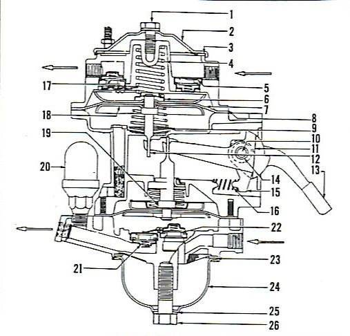
Make
Type
Main Venturi
Primary Venturi
Flange Size
Secondary Venturi
Float Level
Idle Adjustment
Pump Plunger Travel from Closed to Wide Open Throttle
Low Speed Jet Tube
Vent
Gasoline Intake
Idle Port
Idle Port Opening
Idle Screw Seat | Carter WA1-2009S
Single Throat Down Draft
1-3/8"
11/32" I.S.
1-3/8"
11/16" I.D.
1/2"
1/2 to 1-1/2 turns open
16/64"
Jet Size No. 65 drill.
By-pass size No. 53
(.0595") drill.
Economizer, in body
.0545"-.0555" diamter.
Idle bleed, size No. 53
(.0595") drill.
Outside only No. 10 drill.
Square vertical needle.
Length .165", Width .030".
.120" to .124" above valve
with valve tightly closed.
No. 46 drill. |
|
Main Nozzle
Metering Rod Jet
Metering Rod
Metering Rod Setting:
Accelerating Pump:
Pump Adjustment
Choke:
Anti-Percolator Valve
Vacuum Spark Port: | Slip nozzle, flush type, (angle tip)
seats in primary venturi
at 45° angle.
Discharge jet size .110" diameter
inner nozzle (seats in slip nozzle).
.1015" Diamter
(75 - 864)
Use Gauge J-1265 Carter T-109-102
Pressure type spring operated lever
with adjustable stroke.
16/64" plunger travel. (Medium
stroke). Use gauge No.T-109-117S
Climatic control, set 1 point lean.
Butterfly type, offset valve. Choke
heat suction hole in body, size
No. 40 (.098") drill.
Saxophone Key
.051" - .054" diameter. Bottom of
port .020" above valve. |
|
FUEL ECONOMY
The engine of the Hudson car is designed to give good performance and economy with regular grades of gasoline.
Premium grades of fuel, which have a higher octane rating, permit the use of a more advanced spark timing without knob or "pinging". This will result in improved performance and economy, however, these extra advantages cannot be obtained from this type of fuel unless the sparking timing is advanced. Avoid the use of fuels which tend to fum up quickly as they materially affect the operation of the engine.
There ar many factors that affect gasoline mileage, such as car speed, road conditions, wind velocity, temperature changes, havy traffic and frequent stops. All of these conditions have a direct bearing on the gasoline mileage your car can give. Here are a few suggestions to improve your gas mileage:
- Warm up the engine by letting it idle for a few minutes when starting in cold weather.
- Accelerate slowly and avoid racing the engine.
- Do not drive in low or second speed gears unnecessarily.
- By maintaining as nearly a steady speed as possible in traffic, you will do less gear shifting and apply brakes less frequently.
- Avoid sudden and unnecessary stops. Apply brakes gradually, allow engine to slow down car.
- Keep tires inflated to the recommended pressure.
- Do not idle the engine longer than necessary. Turn off the ignition while waiting at the curb or when delayed at railroad crossings.
- Use engine oil of the proper viscosity.
- Keep your car properly lubricated.
- Have the engine of your car tuned by an Authorized Hudson Dealer each 5,000 miles. He will check its operation and make any necessary adjustments, including ignition timing, contact points, spark plugs, valve adjustment and other important details which have a direct bearing on operating economy.
|
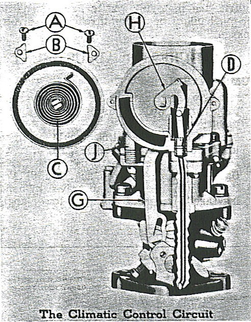
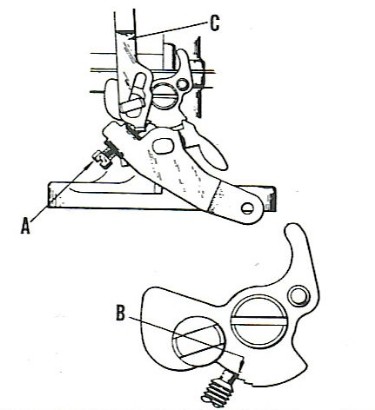
The Climatic Control closes the choke valve when the engine is cold. The Climatic Control is connected to the exhaust manifold by a tube (J-Figure 1) which allows exhaust gases to enter through the opening into the control housing and warm the thermostatic spring (C) and decreases the spring tension. A Vacuum piston (D) is connected to the choke valve and operates from the vacuum of the intake manifold. The pull of the piston against the thermostatic spring opens the choke valve (H) as the engine becomes warm.
A cam on the choke valve shaft is brought against an adjusting screw when the choke is closed.
The screw is adjusted to hold the throttle open sufficiently to procide necessary engine speed (fast idle) during the warm up period.
An unloader (G) is provided in the choke linkage to open the choke valve when the accelerator pedal is fully depressed. This allows the engine to clear itself of excess fuel if the engine is flooded during the starting period.
As the choke valve opens, the fast idle cam moves away from the screw allowing the engine to run at normal idle speed.
|
FIGURE 1
|
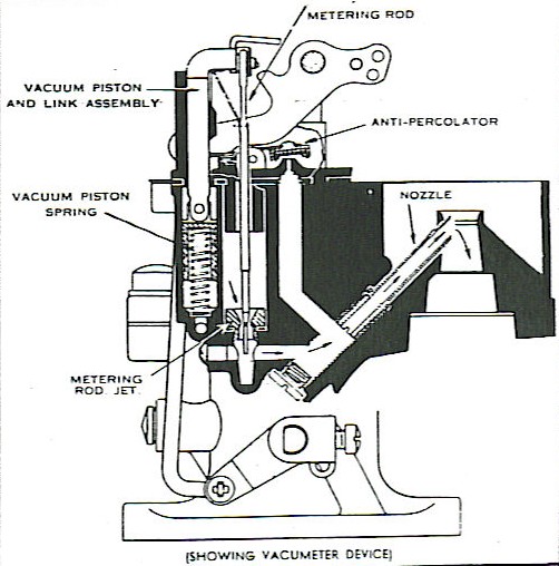
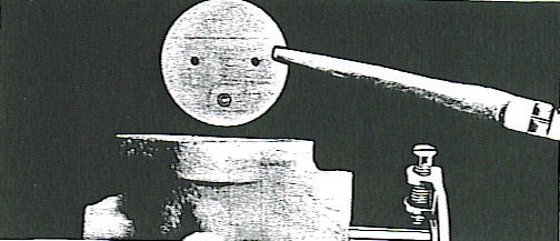
When the car stands in extremely hot weather or after a hard run, fuel in the carburetor bowl may vaporize and set up pressure in the bowl. To prevent this pressure from forcing the fuel out the high speed nozzle (percolating), a saxophone key type anti-percolator valve vents the carburetor bowl to the atmosphere when the throttle is closed, relieving the pressure in the bowl, Figure 2. An anti-percolator valve that opens too early will allow excess air to be drawn into the high speed circuit. If the valve fails to open, it will cause difficult starting when the engine is hot.
|
FIGURE 2
|
The amount of fuel admitted to the carburetor throat through the high speed circuit is controlled by a stepped and taperd metering rod. Figure 2.
Opening the throttle raises the metering rod allowing more fuel to pass through the jet.
At top speed, the smallest section of the metering rod is in the jet.
Under heavy load at part throttle and for acceleration at part throttle, a richer than normal air to fuel ratio is required. To provide this richer mixture, regardless of throttle position, the metering rod is connected to a vacuum piston. Under normal operating conditions the vacuum piston holds the metering rod down against the throttle link. When the engine vacuum drops, a spring under the vacuum piston raises the piston and metering rod, allowing more fuel to flow through the jet. As soon as the engine vacuum rises, the need for rich mixture passes and the vacuum piston returns the metering rod to normal position for mechanical operaton through the throttle linkage.
|
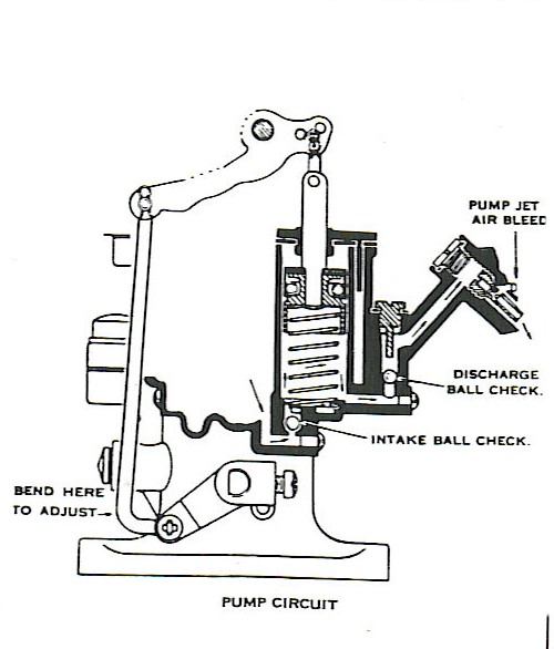
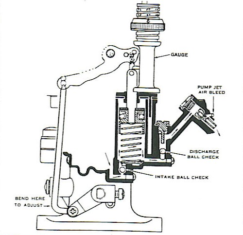
The carburetor incorporates a throttle operated accelerating pump, Figure 3, which discharges additional fuel into the carburetor throat when the throttle is opened. The discharge is prolonged by the pressure of the pump and the restriction of the pump jet. This discharge allows time for the high speed circuit to furnish necessary fuel.
- Remove the carburetor dust cover and back out throttle adjusting screw to seat throttle valve.
- Pump connector link should be in the lower hole (short stroke), Figure 3.
- Pump travel should be 16/64". Use Carter Universal Pump Stroke Gauge T-109-117-S if available. Adjust pump travel by bending throttle connecting link at lower angle. Figure 3.
|
FIGURE 3
|
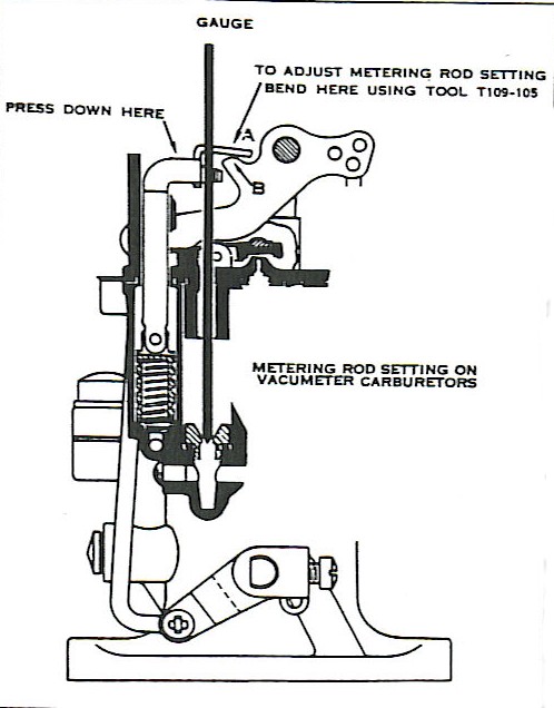
METERING ROD SETTING
- Remove air cleaner and carburetor dust cover.
- Remove hairpin clip and disconnect spring from metering rod and remove metering rod and disk.
- Insert metering rod gauge J-1265 (Carter No. T-109-102). Hold gauge vertical and be sure gauge is seated in metering rod jet, Figure 4.
- Press down on vacuum piston link directly over piston until it contacts the pump arm. Clearance between metering rod pin and shoulder of gauge should be less than .005" with throttle valve seated. Gauge must not drag on pin. Adjust by bending lip on piston link at (A).
- Remove gauge, instll metering rod, disk, and reconnect metering rod spring.
|
FIGURE 4
|
ANTI-PRECOLATOR ADJUSTMENT
NOTE: Carburetor must be removed from engine.
- Crack throttle valve .020" by placing gauge J-1633 (Carburetor No. T-109-29) between throttle valve and bore of carburetor on side opposite the idle port, Figrue 5.
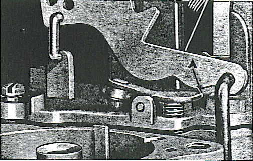
- Clearance between percolator rocker arm lip and pump arm should be .005" to .015", Figures 5 and 6.
- Adjust by bending the rocker arm at (A) Figure 6, using bending Tool J-1389 to obtain this clearance.
|
FIGURE 5
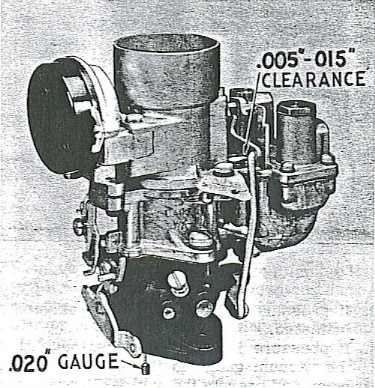 |
FIGURE 6
|
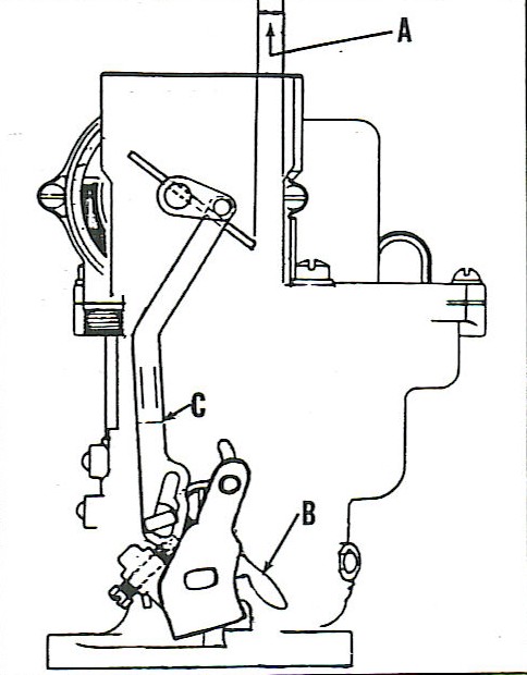
- Remove carburetor air cleaner, open throttle wide open and check between lower edge f choke valve and air horn (A) Figure 7, clearance should be 7/16".
- Adjust by bending cam (B) on throttle lever using Bending Tool J-1137.
|
FIGURE 7
|
- With fast idle cam in normal idle position, tighten throttle lever adjsuting screw (A), Figure 8, until it just seats against the cam.
- Hold throttle lever closed and pull cam back until low step is aginst but not on set screw (B), Figure 8. Clearance between lower edge of choke valve and air horn should be 5/8" (A), Figure 7.
- Adjust by bending fast idle link at offset portion (C).
|
FIGURE 8
|
IDLE ADJUSTMENT
- Start engine and allow engine to warm up.
- See that choke valve is wide open and set idle adjustment screw to obtain smooth idle at 540 to 560 R.P.M. on cars equipped with Standard Transmission (490-510 R.P.M. for cars equipped with Hydra-Matic Transmission).
NOTE: Normal setting is ½ to 1-½ turns open.
- Remove air cleaner and disconnect throttle linkage at carburetor.
- Disconnect gas line from carburetor to fuel pump and disconnect vacuum line from carburetor to distributor.
- Disconnect heat riser tube from exhaust manifold to carburetor.
- Remove nuts and lockwashers from the carburetor mounting studs and remove carburetor assembly.
- Remove fast idle cam and pin assembly.
- Remove air horn and climatic control assembly and lift off air horn gasket.
- Disconnect throttle connector rod; then remove bowl cover with all parts attached. Remove throttle shaft arm assembly.
- Check throttle rod for wear at both ends and at hole in pump arm. Remove bowl cover gasket and pump spring.Remove the metering rod jet and gasket assembly.
- Remove the low speed jet assembly.
- Remove the pump jet plug and gasket assembly and pump jet.
- Remove the pump discharge ball retainer and gasket, and check ball.
- Remove nozzle passage plug, nozzle retainer plug and nozzle. (Be sure to remove small nozzle gasket from casting.)
- Remove the pump strainer and pump instake ball check.
- Separate the body from flange assembly and remove the body flange gasket.
- Remove idle adjustment screw and spring.
NOTE: Check for groove on seating surface.
- Remove idle port rivet plug with rivet extractor KMO-481.
- Remove throttle valve screws, valve and throttle shaft and lever assembly. Check shaft for wear or loose lever and throttle rod hole in lever for wear.
- Remove choke valve screws, choke valve, shaft and piston assembly from air horn. Do not remove the piston housing (attached to the air horn with rivets).
- Remove all parts from the bowl cover.
|
- Clean casting and metal parts thoroughly with a good commercial carburetor cleaning compound.
- Examine each part and replace any part that shows wear. use all new choke gaskets, and new screws on throttle and choke valve.
- Install strainer and strainer nut and gasket assembly.
- Install needle seat and gasket assembly.
NOTE: Check for wear. If either the needle or the seat shows wear, replace both.
- Install the needle, float and lever assembly, and float lever pin. Check float for dents and wear on lip, and float pin for wear. Check bowl cover for wear in hole. Set float lever to ½" by bending lip (A), Figure 9, that contacts the needle. Do not bend float. Measure distance from projection on bowl cover to soldered seam of float.
|
FIGURE 9
|
- Install throttle shaft and lever assembly and throttle valve. Small "C" in circle should be toward idle port facing manifold side of flange. Figure 10. Center the valve by tapping valve lightly before tightening screws. peen ends of screw threads to keep screws from loosening.
NOTE: Back out throttle lever adjusting screw before installing shaft assembly.
|
Figure 10
|
- Install idle port rivet plug.
- Install idle adjustment screw and spring. Back out from seated position ½ to 1-½ turns. (Make final adjustment after installation.).
- Assemble body and flange assembly. Install screws and lockwashers. Pull screws down evenly.
- Install low speed jet assembly. (Be sure jet seats firmly in casting.)
- Install pump jet and pump jet passage plug and gasket assembly. (be sure jet is clear of all restrictions and seats properly.
- Install pump check ball and pump discharge ball retainer and gasket.
- Install pump intake check ball and pump strainer.
- Install pump spring and pump plunger and rod assembly. Examine leather of plunger for damage. If leather is not in good condition, replace entire plunger assembly.
- Install metering rod jet and gasket assembly. Examine for wear. If jet is worn, replace both metreing rod and jet.
- Install the bowl cover assembly. Pull screws down evenly. Install idle passage plug and gasket assembly. (Center of bowl cover).
- Install the anti-percolator cap and rocker arm assembly and spring. (Make certain that leather is in good condition and that pin is not worn.)
- Install pump arm and countershaft assembly. Install connector link on pump shaft in lower hole in pump arm.
- Install the throttle shaft arm and screw assembly and throttle connector rod. Check throttle shaft arm for wear.
|
- With throttle connector rod in place, adjust pump stroke, Use Carter Universal Pump Travel Gauge T-109-117S or machinist scale, Figure 11, and set pump travel 16/64". Adjsut by bending throttle connector rod at lower angle.
- Adjust metering rod after pump adjustment is made. (See Figure 4). Insert metering rod gauge J-1265 in place of metreing rod, seating tapered end in jet. With throttle valve seated, press down lightly on piston link directly over piston. There should be less than .005" clearance between metering od pin and shoulder of notch in gauge. Gauge must not drag by bending lip (A) on piston link so that it contacts hump on pum parm (B). Remove gauge, install rod and disc, and connect spring.
- Adjust anti-percolator as outlined in Anti-Percolator Adjustment section above, Figure's 5 and 6.
- Install nozzle, nozzle retainer plug and nozzle passage plug and gasket assembly.
- Install air horn and piston housing assembly. Install screws and lockwashers. Tighten screws evenly.
- With choke, lever, screw and link in place, install choke shaft and piston assembly. Check for loose lever on shaft.
|
Figure 11
|
- Install choke valve. Center choke valve on shaft and in bore by tapping lightly. Hold in place with finger while tightening screws. Peen ends of screw threads to keep screws from loosening.
- Install the piston housing and thermostatic coil assembly with indicator marks at bottom and rotate counter-clockwise to center graduation.
- Hold choke valve wise open, then tighten the choke lever screw. Be sure that the linkage does not bind in any position. Fast idle, unloader and lockout adjustments should be made as specified under "Carburetor Adjustments".
- Install fast idle cam and pin assembly.
|
CARBURETOR INSTALLATION
NOTE: Place one gasket above and seven below the deflector. Replace broken or damaged gaskets and straighten deflector if damaged.
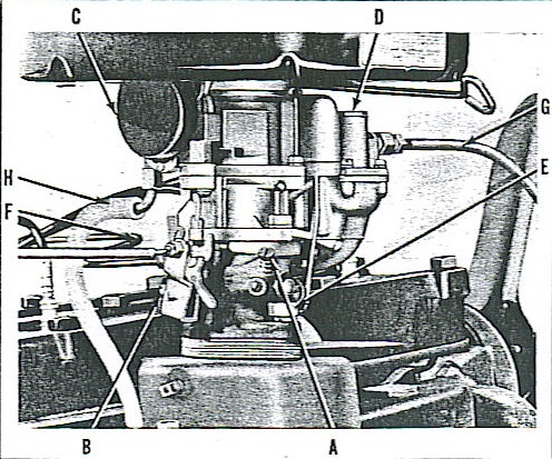
- Install carburetor and install nuts and lock washers on the carburetor mounting studs (E), Figure 12.
- Connect vacuum line from distributor to carburetor (F) and gas line from fuel pump to carburetor (G).
- Connect heat riser tube from exhaust manifold to carburetor (H) and throttle to carburetor, install clamp.
- Adjust and test carburetor for maximum performance.
- Install air cleaner.
NOTE: Do not tighten air cleaner clamp so tight that carburetor air horn will be distorted.
|
Figure 12
|
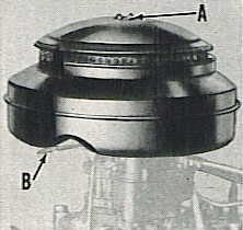
The oil wetted type air cleaner is used as standard equipment on all models. In this type cleaner, the wire gauze is oil-soaked and as the air passes through it, foreign particles are removed. The oil wetted type air filter can be cleaned in the following manner:
- Remove the attaching wing nut (A) at top of cleaner and lift out gauze unit.
- Clean off and remove old oil and dirt by dipping the gauze unit in kerosene. Blow it dry and re-oil by dipping in engine oil, using the same grade as used in the engine.
- Permit excessive oil to drain off and reinstall unit in the cleaner.
|
 |
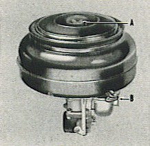
AIR CLEANER - Oil Bath
The oil bath type air cleaner [was] available as an option or [could have been] installed by your Authorized Hudson Dealer. In this unit, dirt is washed out of the air by the oil spray created as the incoming air strikes the oil in the cleaner sump.
- Loosen long clamp type screw at cleaner base (B), lift up and take off complete cleaner.
- Remove the wing nut at top of cleaner (A), lift out filter element (upper section) and wash element in kerosene. DO NOT oil.
- Remove old oil, wash out cleaner base and refill to level indicated with one point of S.A.E. 50 oil at temperatures above 32° and S.A.E. 20 oil at temperature below 32 degrees.CAUTION: Do not fill above level mark.
- Install upper section of cleaner and tighten wing nut.
- Install cleaner, tighten screw moderately tight.
|
 |
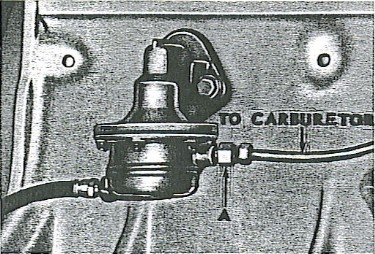
A Carter mechanical fuel pump M-729SZ, Figure 13, is used as standard equipment. A combination fuel and vacuum pump is also available as an option. The pump cam lever (A) fits under an eccentric on the camshaft. Rotation of the camshaft forces the cam lever down against the diaphragm (H). Fuel is drawn into the fuel chamber through the inlet port (L), screen (M), and the inlet valve (I). When the low side of the eccentric is against the cam lever, the diaphragm spring forces the diaphragm down, expelling fuel through the outlet valve (N) and outlet port (K) to the carburetor bowl.
|
Figure 13
|
Continued pump operation fills the carburetor bowl, and the float needle valve closes the carburetor inlet. Fuel pressure built up in the pump fuel chamber opposed the diaghragm spring, resulting in shorter strokes until the pump stops completely. Normal diaphragm stroke is about 1/64".
FUEL PUMP TEST
- Make sure all connections and cover screws are tight after replacement.
- Disconnect the fuel line at the carburetor and connect the fuel pump pressure gauge.
- Start the engine and run at 1800 R.P.M. Pressure should be 4 to 5 pounds. Stop engine and watch pressure gague. Pressure should not fall perceptibly.
- If pressure falls, leaking pump valves are indicated.
- If pressure is below specifications, attach vacuum gauge to inlet port of pump and operate engine. Gauge should show 6" of mercury or higher for satisfactory operation.
- If fuel pump pressure is low, but vacuum reading satisfactory, difficulty is in the gasoline tank or lines to the pump.
- If pump pressure and vacuum are both low, pump should be repaired or replaced.
VACUUM BOOSTER TEST
To check the action of the vacuum portion of the combination fuel and vacuum pump, connect a vacuum gauge to the inlet port and disconnect outlet. Gauge should show 8-½" of mercury at 120 R.P.M. and 12" at 1800 R.P.M. If vacuum is not within these limits, repair or replace pump.
REMOVAL
- Disconnect fuel lines from pump. On combination pump disconnect vacuum lines also.
- Remove cap screws, fuel pump and gasket pack.
FUEL PUMP DISASSEMBLY (CARTER)
- Mark pump body and valve housing with a file to insure correct reassembly.
- Remove cam lever return spring (E), Figure 13, cam lever pin rivet plug (B), retainer (C), and pin (D), and cam lever (A).
- Remove six valve housing screws (F), valve housing (J), the two valve housing cover attaching screws, valve housing cover (O), outlet air dome diaphragm (P), and strainer (M).
- Remove diaphragm assembly (H).
NOTE: Do not remove valve cage assemblies (I) and (N) unless they are to be replaced.
- Clean all parts in gasoline. (Do not use a strong solvent or cleaner on valve housing.)
- Inspect parts for wear.
FUEL PUMP ASSEMBLY (CARTER)
- Assemble strainer (M), outlet air dome diaphragm (P), valve housing cover (O), and attach to valve housing.
- Install diaphragm assembly (H), in pump body with flat spaces on sidews towards port.
- Align mark on pump body with mark on valve housing (J) and install housing, but DO NOT tighten screws.
- Install cam lever (A), pin (D), pin retainer (C), and new rivet plug (B).
- Flex diaphragm and hold in maximum down position and tighten valve housing attaching screws.
- Install cam lever return spring (E).
|
FUEL AND VACUUM PUMP (AC) - DISASSEMBLY
- Mark the vacuum section cover and fuel section cover to insure parts are reassembled in their correct position.
- Hold pump in vise, remove 2 fuel cover screws from opposite sides and insert 2 headless screws No. 10-32 x 1-½". After guide screws are installed, remove balance of screws and vacuum section cover.
- Press down on rocker arm (13), Figure 14 and unhook diaphragm link assembly (9) from inner pump arm (12).
- File riveted end of rocker arm pin (10) flush with steel washer or drill off end with a 3/8" drill. Drive out rocker arm pin. Wiggle rocker arm (13) until link 911) is unhooked from diaphragm shaft (19). Remove rocker arm bushings, arm 913), spring (16), link (15), link (12) and link (11).
- Remove fuel pump cover screw (20), gasket (25), cover (24), gasket (23) and screen.
- Remove screws attaching fuel section to center section and remove fuel section, diaphragm (19), valves (21) and (22).
Editor's Note: The pump pictured is for 1948 to early 1953 Hudsons. Pumps changed a couple of months into the 1953 run to AC/AJ. The new 53-54 pumps don't have cover screw bolts (1). The non-vacuum Carter M-729-SZ was standard on the Jet, with the upgrade to the AC.
|
Figure 14
|
ASSEMBLY
- Assemble link spacer (15) over fuel link (11). Place one vacuum link (11) and (12) on each side of the fuel link. The hook ends of the vacuum link should come together so that they surround the fuel link. All link hooks should point in the same direction. Place assembly of links and spacer between lobes of rocker arm with one spacer washer on the outer side of each vacuum link. Slide rocker arm bushing (14) through holes in rocker arm spacer washers and links. Retain the parts in position by using AC Tool PT-6 or a long straight 3/16" pin.
- Place diaphragm spring in position and assemble pull rod and diaphragm assembly (19) through boss in fuel body, hooking pull rod over end of link.
- Drive out tool PT-6 with a new rocker arm pin (10). Place washer over small end of new pin and spread pin end with a round nose ounch.
- Place valve and cage gaskets in recesses on fuel cover. Inlet valve must have three legged spider facing out of cover, outlet valve must have three-legged spider facing into cover. Install retainer and screw.
- Install strainer screen, bowl gasket (23), bowl (24), bowl screw gasket (25) and bowl screw (26). Install air dome (20).
- Install fuel cover on body, making sure that file marks on cover and body line up. Push on rocker arm until diaphragm is flat across body flange. Install cover screws and lockwashers loosely until screws just engage lockwashers. Pump the rocker arm three or four full strokes and tighten cover screws alternately until secure. Diaphragm must be flexed before tightening cover screws, or pump will deliver too much pressure.
- Place two gaskets and two valves and cage assemblies (17) and (5) in cover. Secure valve and cages with retainer and screw.
- Turn cover over and set screen in recess over valve hole. Set screen retainer on screen. Place cover gasket (3), cover (2), cover screw gasket and cover screw (1) in position and tighten cover screw. [Cover screw (1) simply holds the cover to the vacuum booster diaphram assembly.]
- Assemble oil seal on vacuum diaphragm pull rod in the following sequence: oil seal spring, upper retainer, oil seal washer, and lower retainer. Turn lower retainer 90 degrees to lock in position.
- Lift the pump body above eye level, facing the vacuum diahragm flange. The two vacuum links will swing down so that the diahragm pull rod can be hooked to both links.
- While holding vacuum diaphragm in position, the body should be clamped in a vise, vacuum side up. Clam by one of the mounting flange ears. The vacuum diaphragm must be held level with body flange during the followig operations by insertig a 3/32" piece of metal between rocker arm stop and body. This spacer can be made from a piece of seel, 3/16" to 3/32" by 8 inches. Bend one end to form a right angle hook, 3/8" from bend to end. (This tool is available from your AC jobber as tool PT-8).
- Place spring retainer on riveted end of diaphragm pull rod, and place spring on the retainer. Place vacuum cover and valve assembly over spring and align the file marks.
- Insert the two No. 10-32 x 1-½' screws i opposite holes in ocver flange. Turn these long screws down as far as they will go without forcing, alternating a few turns on each. Insert regular screws with lock washers and tighten until screws just engage lockwashers. Place two long screws with regular screws and lockwashers.
- Remove 3/32" spacer from rocker arm position. This allows the heavy vacuum spring to push diaphragm into a flexed position. Tighten all cover screws alternately until secure.
- Combination fuel and vacuum pump cannot be bench tested because of the heavy vacuum spring. Use a vacuum gauge and test pump while pump is assembled to engine.
INSTALLATION
Install in reverse order of removal. Make sure the flange gasket, mounting stud insulator bushings and washers are installed properly.
|
The fuel level indicator is of the constant voltage type. It consists of a voltage regulator, panel indicator and a tank level unit connected by a single wire system between the units. Figure 15.
VOLTAGE REGULATOR
Its function is to regulate the variable (input) voltage available from the car storage battery, or the charging system, to produce a constant 5.0 volt output to the gauges. This regulator is a simple device, operating with a heater bimetal in conjunction with a pair of contacts.
Editor's Note: The heater bimetal is made by laminating two different types of metal together. Each type of metal has its own particular rate of expansion.
|
Figure 15
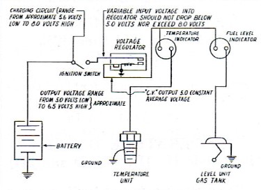 |
FUEL LEVEL GAUGE
[As resistance is decreased (by filling gas tank), the bimetallic strip is heated and one metal expands less than the other, so the strip curves. This bending action is what moves the needle.] With the tank full, the slide rheostat is moved to the minimum resistance point causing the gauge to read "Full" with the ignition switch on. The use of the bimetal in the fuel indicator provides stability of reading and eliminates pointer fluctuation incidental to surging in the tank and the float bobbing on the surface of the fuel.
[As resistance increases (by consuming fuel), less current passes through the heating coil, so the bimetallic strip cools. As the strip cools, it contracts and straightens out, pulling the gauge from full to empty.] With the tank empty, the float holds the slide rheostat (variable resistance) at maximum resistance causing the gauge to read empty.
|
GAUGE TROUBLE DIAGNOSIS
GAUGE TESTING EQUIPMENT
One new OK tank level unit (constant voltage type), one new OK panel fuel indicator gauge and three ten-foot length of No. 16 insulated wire equipped with clip terminals at each end of wire.
VOLTAGE REGULATOR
The constant voltage regulator is common to both fuel and temperature system, that is, one regulator, is used to operate both systems, Figure 15.
|
METHOD OF CHECKING
- If both gauges read considerably too high - for example, if the gas guage reads up the scale with an empty gas tank and the temperature gage reads up scale with a cold engine, the constant voltage regulator is not working properly and should be replaced: (Check ground connections of the voltage regulator as grounding is essential to the proper functioning of the regulator.)
- If both gauges read too low, either the input voltage to the C.V. regulator is below 5.0 volts or the voltage regulator is inoperative and should be replaced. Check battery voltage output before replacing regulator.
PANEL INDICATOR (FUEL GAUGE) CHECK
- Disconnect lead wire at gas tank gauge unit.
- Hook in a new tank unit of proper calibration. See Figure 16. Ground tank unit. Place float in empty position. Turn on ignition switch. Panel gauge should read at (E) on dial.
- Move float to full position, panel gauge should read full (F).
NOTE: If check 2 and 3 are OK, both panel gauge and lead wire are OK. If checks 2 and 3 are not OK, hook up a new tank unit to proper terminal of panel gauge and eliminate the lead wire from the panel indicator to the unit from the regulator circuit. Repeat emtpy and full check. If now operating OK, correct or replace bad wire between tank unit and panel gauge.
Editor's Note: The float mechanism is one reason for the inaccuracy of fuel gauges. You may have noticed how your gauge tends to stay on full for quite a while after filling up. When your tank is full, the float is at its maximum raised position -- its upward movement is limited either by the rod it's connected to or by the top of the tank. This means that the float is submerged, and it won't start to sink until the fuel level drops to almost the bottom of the float. The needle on the gauge won't start to move until the float starts to sink.
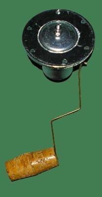
GAS TANK UNIT CHECK [aka Sending Unit]
Editor's Note: The fuel pickup tube on Jets are SEPERATE from the fuel sending unit.
If there is any question about the tank level unit being OK, hook the tank unit up in series with a panel indicator and a constant voltage regulator known to be OK and a six bolt battery. Operate tank level unit by hand and see if panel indicator reads emty (E) with tank level unit float in bottom position, and reads full with level unit float in top position. If the panel indicator and lead wire function properly with a new OK tank unit, but did not function properly with original unit, replace original unit.
NOTE: Be sure tank unit is properly grounded to gas tank and also that the tank is grounded to the frame.
REPLACING FUEL SENDING UNIT (Per website editor.)
BEFORE PROCEEDING: Disconnect negative terminal on battery to avoid spark. Syphon/Drain gasoline from tank.
There is a single wire leading to a nut. Loosen nut. Remove prong-end wire. The original sending units are a "twist-lock" type. You'll see a few notches along the outer ring of the sending unit. Place the tip of a sturdy flat head screwdriver in the notch and gently tap it counter-clockwise. The sending unit will rotate until it's loose. Now you can remove the fuel tank sending unit in one piece. Attached to it is a long rod with a float at the end, so you might have to try a couple of different angles to get it out. See Replacement Parts List below for sources to purchase replacement sending unit. As usual, installation is the reverse of removal. Don't forget to re-attach wire to the sender. Failure to do this will result in the Fuel Level Indicator reading Empty.

REPLACING CORK FLOATS on FUEL SENDING UNIT (Per website editor.)
Inaccurate Fuel Level Indicator readings may be caused by a faulty float on the fuel sender. Henry Votel has an excellent step-by-step guide on replacing your cork float with a brass one, using Ford part number COAZ-9202-B ($5-$10).
REMOVAL
- Raise car and drain the gasoline tank and disconnect the fuel gauge wire and fuel line.
- Remove the two nuts and washers attaching gas tank straps to rear compartment floor and remove gas tank.
- Remove the gas tank gauge unit and gas tank outlet pipe.
INSTALLATION
- Install gas tank gauge unit (use new gasket).
- Install outlet tube and install gas tank.
- Install gas tank straps and draw tank up into position.
- Connect gauge wire and fuel line and lower car.
EXHAUST AND INTAKE MANIFOLDS
REMOVAL
Remove both manifolds as a single unit.
- Remove air cleaner by loosening the attaching screw at the carburetor air horn.
- Disconnect the throttle rod at carburetor.
- Remove the fuel line, vacuum line and heat riser tube from carburetor.
- Remove the two bolts attaching exhaust pipe flange to exhaust manifold.
- Remove the eight nuts, four washers, and four retainers attaching manifolds to block and remove manifolds with carburetor attached.
INSTALLATION
Reverse the procedure of removal.
ALL HUDSON MODELS
as suggested by A.E. Adams, Technical Service Editor,
in Technical Service Bulletin TS 77-2 by Hudson Motor Car Company, Detroit, Mich., U.S.A.
This article from the Hudson Service Merchandiser dated May 1952, is reproduced with the thought of emphasizing this point also for the benefit of any new men in the service field.
Perhaps no other important part of a gas engine is overlooked or neglected as much as the Exhaust Manifold Damper.
Although the Exhaust Manifold Damper Shaft is of a heat-resisting steel, it sometimes sticks or becomes so tight due to carbon build-up that the springs, thremostat or counter-weight will fail to move it.
When the damper action become sluggish or sticks, the results are a very slow warm-up and poor performance in winter if stuck at the "heat off" position.
If stuck at the "heat on" position and the atmospheric temperature is high, engine power falls off and performance becomes sluggish. A sharp, responsive Exhaust Manifold Damper is important and accentuates engine tuning.
Should the Damper Shaft be found to be stuck, remove the thermostat and springs, apply penetrating oil or kerosene and tap the shaft for end play to break the carbon and corrosion. The shaft should not be oiled. When properly freed, carefully check springs and thermostat before installing and replace them if weak.
REMOVAL
NOTE: For removal, follow same procedure as exhaust manifold removal and, in addition the following operation.
- Disconnect outer spring and reatiner and remove heat control spring.
- Remove the two nuts holding cover to manifold. Remove cover and anti-rattle spring.
- Use a drift to remove the tapered pin. This will allow removal of the shaft and butterfly.
INSTALLATION
Reverse procedure of removal.
REMOVAL
- Raise car.
- Remove two bolts attaching exhaust pipe flange.
- Remove bolt and nut from bracket attaching exhaust pipe to engine support plate.
- Remove bolt and nut and clamp attaching exhaust pipe to auxiliary muffler.
- Disconnect exhaust pipe and remove from under car.
NOTE: Forcing the auxiliary muffler to the rear on the mounting will help in the removal of the exhaust pipe.
INSTALLATION
- Install new front exhaust pipe from under car, and connect at front of auxiliary muffler, do not tighten clamp.
- Install clamp at engine support plate but do not tighten.
- Connect exhaust pipe flange to exhaust manifold and tighten securely.
- Tighten clamps at auxiliary muffler, also at engine support plate.
Q: Are fuel tanks and senders being reproduced?
A: I don't know of any vendors offering new fuel tanks. However, your original tank can be sent to Moyer Fuel Tank, who uses the RENU repair and coating process. See Replacement Parts List for fuel sending units.
Q: Why am I seeing fuel leakage around the tops screws on my fuel pump?
A: A reason gas is coming through the screw holes is because the fuel diaphram is "soaking". The fuel is not being repelled by the diaphram material any longer and is acting like a sponge. The pump needs rebuilding. The ethanol in the fuel is a large cause of this. Consider sending it to Then & Now Automotive, 447 Washington Street, Weymouth, MA. It will probably be the last time you will ever have to rebuild the pump, for $125. Call them at (781) 335-8860.
Carburetor: Carter: 1 Carb Setup WA1-2009SA, 2 Carb Setup WA1-2013S
Fuel Pump: Carter #MO658, M729SZ (Fuel Only)
Fuel Sending Unit (Entire Unit): #AK02121153 RTSC from Atwater Kent Manufacturing Company at (508)792-9500
Fuel Sending Units can be rebuilt and repaired by TriStar Radiator, who also carry new, used & rebuilt fuel sending units.
Fill up at an Ethanol-Free gas station! List of stations!
|
|
|
|
Courtesy HET JetSet - All Rights Reserved.
|
|