Hudson Jet |  |
DISCLAIMER: Unless otherwise noted, service information has been provided by an edition of the Mechanical Procedures Manual for Jet models. The data from the Manual includes information covering specifications, adjustments and detailed operation involved in maintenance and repair procedures. After market updates from Hudson Service Merchandisers and other sources have been added as well and are credited in italics. HudsonJet.net provides this reference as a courtesy and is not responsible for any work done using Hudson Motor Car Company's publications or other sources provided on this site. |
|
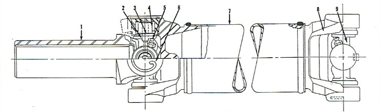
FIGURE 1 |
- Sleeve yoke - front
- Dust washer retainer
- Dust washer
|
- Bearing assembly
- Grease fitting
- Snap ring
|
- Propeller shaft
- Yoke - rear
- Rear universal joint
|
|
The single propeller shaft is of tubular construction, fitted with needle roller bearing universal joints at front and rear end. The font joint carries a splines sleeve yoke which slides on the rear end of the transmission main shaft to compensate for rear axle up and down movement. The needle bearing cups are retained by lock rings inthe front joint and by lock rings in the front joint and by lock rings and 'U" bolts in the rear joint.
Universal joints are provided with means of lubrication for the needle roller bearings by grease fittings and should be lubricated with 140 S.A.E. Mineral Oil every 1000 miles.
NOTE: Sliding front yoke receives lubrication from transmission.
REMOVAL
- Raise car on hoist or jack stands.
- Remove nuts, lock plates, "U" bolts from the rear universal joint at the rear axle companion flange (tape needle cups to prevent bearings from coming apart). Lower rear end of propeller shaft and pull complete assembly backward out of transmission. Place assembly on work bench for servicing.
NOTE: With the propeller shaft removed, inspect the rear transmission oil seal and replace if worn, damaged or shows signs of oil leakage.
When disassembling the universal joints inspect for wear, proceed as follows:
- Compress and remove snap rings holding bearing cups in place.
- Use a brass drift and hammer and tap on one bearing cup carefully to drive out the opposite cup.
- With a brass drift, tap on the end of the journal from which the bearing was just removed and remove the remaining bearing cup and rollers.
After both joints are completely disassembled clean parts and carefly inspect for damage and wear. If the journals of the crosses and the needle bearing cups show signs of wear or brinneling or if the needle rollers are tightened or undersize the parts must be replaced. It is also advisable to replace the oil seals between the bearing cups and the joint crosses replace lock rings if they hae lost their tension or are burred or mutilated.
|
- Use new oil seals on the inner side of the journals.
- Apply a generous quantity of viscous chassis lubricant to the journal working surfaces and to the inside of th needle bearing cups. Place needle rollers i position against inside of cups.
- Hold the yokes and journals so the bearing cup assemblies can be inserted from the bottom.
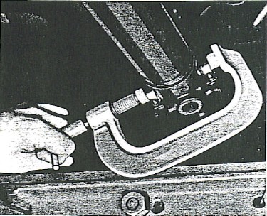
- The rollers will not be dislodged if the bearing cups are installed from the bottom. Press bearing cups into place with tool J-881-A, Figure 3.
- Install the journal bearing cup snap rings.
The front and rear universal joint journals should be installed so the grease fittings are in alignment to simplify lubrication.
|
FIGURE 2
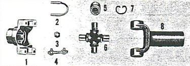 |
- Companion flange
- Propeller shaft U bolt
- Propeller shaft U bolt nut
- Propeller shaft U bolt nut
- Propeller shft U bolt lock
- journal bearing assembly
- Journal
- Journal bearing race snap ring
- Sleeve yoke assembly
|
NOTE: The propeler shaft used on both standard transmission and overdrive transmission models is 50-3/8" long from center to center of universal joints. The shaft used on cars equipped iwth Hydra-Matic Drive is 51-3/4" long - center to center.
- Raise propeller shaft and support yoke and slide into spline on rear of transmission. The sleeve yoke is ahead of the front universal joint; therefore, it canbe installed in any position on the transmission mainshaft splines.
- Connect rear universal joint to companion flange.
NOTE: Journal bearings must be compressed to allow edge of bearing to clear lip at edge of companion flange, otherwise the needle bearing cups will not be properly seated and may come out. Also the propeller shaft will not be in balance. (Tool J-881-A will facilitate assembly.)
- Propeller shaft "U" bolt nuts should be tightened to 20 to 25 puonds torque.
- Raise car, remove stand jack, if used and lower car.
| FIGURE 3
|
|
|
|
Courtesy HET JetSet - All Rights Reserved.
|
|