Hudson Jett |  |
DISCLAIMER: Unless otherwise noted, service information has been provided by an edition of the Mechanical Procedures Manual for Jet models. The data from the Manual includes information covering specifications, adjustments and detailed operation involved in maintenance and repair procedures. After market updates from Hudson Service Merchandisers and other sources have been added as well and are credited in italics. HudsonJet.net provides this reference as a courtesy and is not responsible for any work done using Hudson Motor Car Company's publications or other sources provided on this site. |
|
Figure 1
|
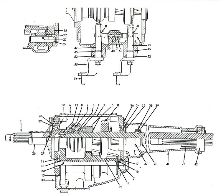
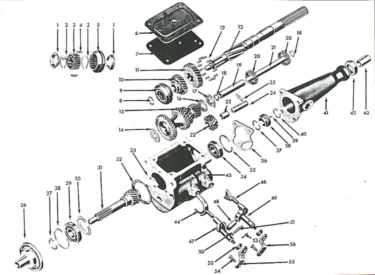
Figure 2
|
| LEGEND |
- Synchronizer rings:
Part# BT 307731 - 2 per car
- Synchronizer springs:
Part# BT 307733 - 2 per car
- Synchronizer hub: Part only supplied in complete Synchronizer Assembly, see #9.
- Synchronizer shift plates:
Part# BT 307732 - 3 per car
- Synchronizer sleeve: Part only supplied in complete Synchronizer Assembly, see #9.
- Tranny Cover: Part# BT 307768
- Cover gasket: Part# F 307770
- Main shaft snap ring:
Part# BT 307730
- Synchronizer shift sleeve assembly: Part# BT 307727
- Second speed gear and bushing:
Part# F 307724
- Low and reverse gear: Part# F 307737
- Mainshaft front rollers:
Part# BT 307738
- Mainshaft
- Less OD: Part# BT 307720
- With OD: Part# BT 307722
- C.S. thrust washer (front):
Part# BT 307743 (Bronze)
- C.S. gear cluster-33 teeth on large gear: Part# F 307741
- C.S. rear thrust washer (inner):
Part# BT 307744 (Bronze)
- C.S. rear thrust washer (outer):
Part# BT 307745 (Steel)
- C.S. bearing washer:
Part# BT 307746 -2 per car
- C.S. gear spacer: Part# BT 307742
|
- C.S. bearing rollers:
Part# BT 306829 - 40 per car
- Counter shaft: Part# F 307740
- Reverse idler gear: Part# F 307747
- Reverse idler gear bushing:
Part# BT 307748
- Reverse idler gear shaft:
Part# BT 307750
- Idler and C.S. lock plate:
Part# BT 307751
- Drive gear bearing retainer:
Part# BT 307714
- Drive gear snap ring
- Bearing snap ring
- Drive gear bearing:
Part# F 306786 (Federal 1207CG)
- Oil retaining washer:
Part# BT 306799
- Main Drive gear:
Part# F 307705 (24 teeth)
- Bearing retainer gasket:
Part# BT 307715
- Transmission case
- Less OD: Part# F 307723
- With OD: Part# F 170409
- Mainshaft bearing (rear)
- Less OD: Part# C 307700
- With OD: Part# C 307702
- Mainshaft bearing snap ring
- Bearing retainer gasket:
Part# BT 307718 (less OD)
- Speedometer gear snap ring (front)
- Speedometer gear
|
- Speedometer gear lock key
- Speedometer gear snap ring (rear)
- Mainshaft bearing retainer
- Mainshaft oil seal
- Mainshaft bushing
- Shift fork (second and high):
Part# BT 307758
- Taper pin:
Part# BT 301859 - 2 per car
- Shift fork (low and reverse):
Part# BT 307755
- Shift shaft (second and high):
Part# BT 307756
- Shift shaft interlock sleeve:
Part# BT 306843
- Shift shaft (low and reverse):
Part# BT 307752
- Shift rail lock ball:
Part# BT 534 - 2 per car
- Shift rail lock ball spring:
Part# BT 306848
- Shift shaft oil seal:
Part# BT 301753 - 2 per car
- Shift lever interlock pin:
Part# BT 306842
- Control lever outer clevis pin
- Second and high control lever (outer):
- LHD: Part# C 307765
- RHD: Part# C 307954
- Low and reverse control lever (outer): Part# BT 307763 (LHD)
|
|
|
GEAR RATIOS |
Low
Second
High
Reverse |
2.605:1
1.630:1
1.000:1
3.536:1 |
|
SNAP RING THICKNESS
Main Drive Gear Bearing = .073" and .076"
Main Drive Gear = .087", .090", .093", .096" and .103"
Mainshaft Bearing Rear = .073" and .076"
Mainshaft Rear Bearing = .087", .090", .093" and .096" |
INTERLOCK SLEEVES |
"A"
"B"
"C"
"D"
No Marking
|
1.295"
1.291"
1.287"
1.303"
1.299" |
|
LUBRICATION
Transmission - 1-1/2 Pts.
S.A.E. - 90 Summer
S.A.E. - 80 Winter |
The transmission is of the all-helical gear type with synchro-mesh second and high gears.
The rear of the main drive gear is supported by a ball bearing mounted in the transmission case and the front end pilots in a bronze bushing. The front end of the mainshaft operates in rollers carried in the main drive gear and the rear end of the mainshaft is supported by a ball bearing mounted in the case. Oil retention is by means of a hydraulic leather oil seal in the rear bearing retainer.
The mainshaft second speed gear and the reverse idler gear operate on their shafts through precision fitted, bronze alloy bushings. The countershaft gear cluster operates on the stationary countershaft through needle rollers at each end held in position by a spacer tube and washers. Countershaft gear cluster end thrust is taken by a single stationary, bronze faced thrust washer at the front and by a rotating bronze washer and a stationary steel washer at the rear.
Separate shift shafts with integral cams on the insdie and actuating levers on the outside, operate the low and reverse and second and high gears through forks and an interlock arrangement common to both shafts. Separate rubber mounted rods connect the outer shift shaft levers to the levers on the transmission control.
The transmission is mounted at the front on the clutch housing with four bolts passing through lugs on the transmission case form the rear into the clutch housing. This simplifies transmission removal and replacement since the clutch housing and floor cover do not have to be disturbed.
The main drive gear bearing retainer positions the transmission in a machined locating hole in the clutch housing.
Breathing or venting is through a small opening in the front of the cover and two holes in the rear of the gasket, which is held away from the cover at the center by a depression stamped in the cover.
- Drain transmission lubricant.
- Disconnect the universal joint at the rear axle companion flange, push propeller shaft forward to release bearing cups from seats in companion flange, then pull propeller shaft rear-ward to release the sleeve yoke from rear end of transmission and remove complete propeller shaft. Use tape around bearing cups to retain cups and rollers in position.
- Disconnect the low and reverse, and second and high shift rods at the transmission shift levers.
- Disconnect speedometer cable at transmission and remove the speedometer pinion.
- Remove the two screws attaching the clutch corss shaft support assembly to the transmission case and remove the support
- Using a universal socket on a 10" extension, remoe the two top bolts attaching the transmission to clutch housing and insert two guide studs (J-2969) to guide transmission during removal.
- Lower the transmission and clean the outside thoroughly before disassembly.
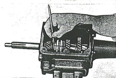
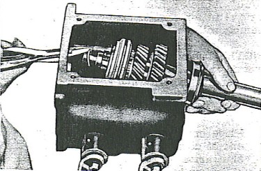
- Remove the four cover screws and remove cover (6) and gasket (7), Figure 2.
- Remove the four bolts from the mainshaft rear bearing retainer (41) and remove retainer and gasket (36).
NOTE: The rear bearing retainer has a reamed bushing at the rear end of the retainer and care should be used when removing the retainer.
|
- Remove the snap ring (40) at the rear of the speedometer gear, remove the speedometer gear (38), key(39) and snap ring (37).
- Remove the three bolts attaching the main drive gear bearing retainer and remove retainer (26) and gasket (32).
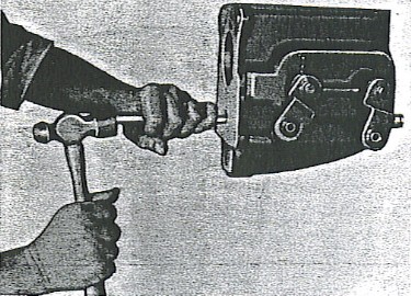
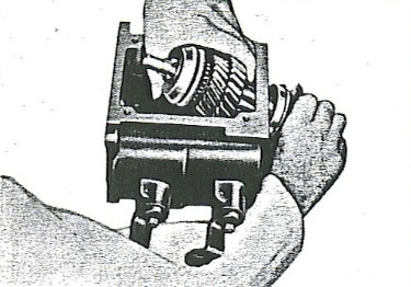
- Using a brass drift and hammer (Figure 3), drive countershaft rearward enough to free the lock plate in the shaft recess and remove lock plate.
- A dummy shaft is necessary to replace the countershaft in the transmission gear cluster to allow shaft and gear cluster to be lowered to bottom of case for removal of the main drive gear.
|
Figure 3
 |
The dummy shaft can be made from a piece of 11/16" diameter cold rolled steel and cut to exactly 5-7/8" long and drill a 3/16" diameter hole 1" deep in each end to provide a means of raising the cluster assembly with two small punches.
NOTE: The purpose of the dummy shaft is to retain in position the needle rollers, spacer and thrust washers when removing and installing the countershaft cluster gear.
- Place end of dummy shaft against front end of coutnershaft, and with a soft hammer, drive the countershaft to the rear out of transmission case.
NOTE: Be sure the dummy shaft remains in constant contact with the countershaft during this operation; otherwise, the thrust washers and needle roller will fall out of place.
|
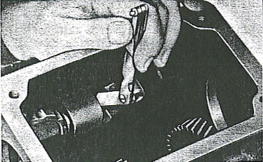
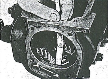
- Use a small pointed brush and paint a fine line across the synchronizer rings, sleeve and second and high gear to insure reassembly of these parts in their proper location, Figure 4.
- In removing main drive gear, use a brass drift against the rear face of the drive gear teeth (not synchronizer teeth) and carefully drive gear and bearing foward out of case.
- Use the same brass drift on the pilot end of the mainshaft and drive mainshaft rearward to remove mainshaft bearing from rear of case.
|
Figure 4
 |
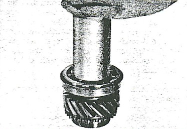
- Use snap ring pliers to remove snap ring from front of mainshaft, Figure 5.
|
Figure 5
 |
- Hold the synchronizer assembly and the second and low gears together asa unit and move mainshaft assembly to the right of transmission case as far as possible to disengage the high and intermediate shifter fork from the synchronizer collar and the low gear. Turn mainshaft and while holding the gears withdraw the mainshaft through through the gears and out of rear of case, Figure 6.
- With a long curved brass drift, drive the reverse idler gear shaft out of rear of transmission case and remove the idler gear.
- Lift the countershaft gear cluster up and out of case. Be careful dummy shaft does not slide out and spill he needle rollers, roller washers and thrust washers.
Note the position of the front and rear thrust washers to insure exact replacement.
|
Figure 6
 |
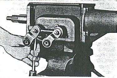
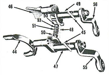
- Using a pin punch, drive taper pins securing shift shafts up and out of case, Figure 7.
- Remove the nuts, washer and levers (55) and (56), Figure 2, from shift shafts (47) and (49) and remove shafts from case. The interlock balls (50), sleeve (48), spring (51) and pin (53) may also be removed.
|
Figure 7
 |
Thoroughly clean and carefully inspect all parts for wear, nicks, scores, etc., to determine if any parts need replacement.
Regardless of appearance, all oil seals and gaskets should be replaced to prevent the possibility of oil leaks.
To replace the mainshaft rear oil seal (42), drive old seal from rear flange and install a new seal, tapping it into bearing retainer from rear of retainer using Seal Installer Tool J-1354.
The rear face of the seal projects 1/4" out of retainer when properly installed.
The shift shaft oil seals (52) are replaced by driving the old seals out from inside of transmission case and driving new ones in from outside of case.
NOTE: When installing new oil seals, it is good practice to coat the outside diameter of the seal and the inside of the housing with white lead or gasket sealer to prevent oil leaks. Leather seals must be soaked in engine oil for 24 hours before using.
The mainshaft second speed gear (10) and the reverse idler gear (22) fitted with bronze bushings must be replaced with a gear and bushing assembly if excessive wear is noted, since replacement of bushings in the field is impracticable.
If the main drive gear ball bearing (29) or the mainshaft rear bearing (34) appear rough or show excessive wear or damage, they should be replaced, using remover J-1134-H with thimble removed. Figure 8 and replacer J-2995-1, Figure 9.
|
Figure 8
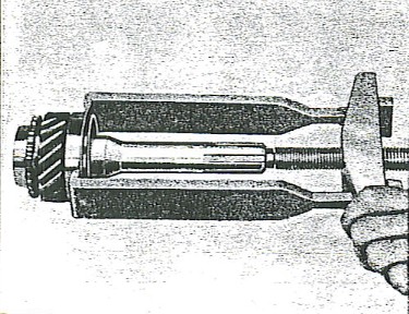 |
Figure 9
 |
- Install the low and reverse shift shaft (49), Figure 2 or 10, in the transmission case. Use care to avoid damage to the oil seal, align the neutral detent of the cam with the interlock boss opening in transmission case and install the taper pin (45) through shift shaft case.
NOTE: It is necessary to install low and reverse shift shaft (49) first due to interference by the boxx of the reverse idler gear shaft.
- Install interlock sleeve in case and insert an interlock ball in sleeve. Then install the sleeve spring (51) and pin (53), Figure 10.
- Install the second and high shift shaft (47) in case and move shaft toward outside of case as far as possible. Install the other interlock ball (50) in the sleeve compressing spring as far as possible; then slide the shift shaft toward center of case aligning neutral detent with interlock ball. Install the taper pin (45) through shift shaft and case.
|
Figure 10
 |
- Install shift shaft levers, short lever (56) (low and reverse) on rear shaft (49) and long lever (55) (second and high) on front shaft. Shift either lever into any gear and with one end of interlock contacting the shift shaft cam, use a feeler gauge as shown in Figure 11 and check the clearance at opposite end of interlock sleeve and cam.
Clearance should be .001" to .007". If not within these limits, the sleeve must be removed and replaced with one of proper length. Consult the "Specifications" above for sleeve dimensions.
|
Figure 11
 |
- To assemble the countershaft gear cluster, insert the dummy shaft and needle roller spacer (19), Figure 2, in the gear cluster (15). Stand assembly on one end apply vixcous grease between shaft and bore of gear cluster. Insert 20 rollers (20) and place the second roller washer (18) on top of rollers. Turn assembly end for end and perform same operation.
- Cover the thrust washers (14), (16), and (17) and ends of gear cluster with viscous grease and place thrust washers in position. The front washer (14) has bronze face to gear and lup to top. Rear washer (16) (inner) bronze must be installed so the two lugs in center of washer engage cluster gear and the (outer) steel washer (17) with the lug to top.
- With cluster gear assembly complete on the dummy shaft, carefully lower the assembly into the transmission case.
Position the assembly with the countershaft holes in case and start countershaft through rear of case. Tap the countershaft forward and keep in constant contact with the dummy shaft to prevent rollers and washers form becoming dislodged.
Drive the countershaft forward just far enough to enter front end in front of case since it must be removed again after checking end play. |
- Insert a feeler gauge between the two rear thrust washers to check gear cluster end play, which should be .006" to .016". If clearance is mroe, the thrust washers should be replaced, Figure 12.
- Enter the dummy shaft into front of case and tapping lightly with a soft hammer, drive the countershaft out through rear of case, being careful to keep both shafts butted together at all times. Then lower the gear cluster assembly with dummy shaft to bottom of case.
|
Figure 12
 |
- Install idler gear (22), Figure 2, in position (long hub to front), and drive in idler gear shaft (24) with slot for lock place in position for alignment with slot in the countershaft. Do not seat shaft tightly since it may be necessary to turn it when countershaft is installed. Idler gear end play tolerance is .003" to .010".
- Install the mainshaft bearing on the mainshaft so that inner race of bearing bottoms against end of spiral splines and install the proper thickness span ring. These snap rings are furnished in five thicknesses. See "Specifications."
- Insert the mainshaft and rear bearing assembly through rear of transmission case and install the low and reverse sliding gear (11) with the shift collar to rear of case.
- Install the low and reverse shift fork (46) (offset to rear) and engage fork in collar of low and reverse sliding gear (11).
- Install the second speed gear (10) and assemble the synchronizer clutch hub, shift plates, shift sleeve, springs and synchronizer rings and install the assembly on the mainshaft with the long hub of the clutch hub to front of transmission.
NOTE: When installing synchronizer springs (2), the hooked ends of both springs must engage the same shift plate on opposite sides.
- Install the mainshaft snap ring, Figure 5, retaining the gears in position and check end play of the second gear by inserting a feeler gauge between the rear face of gear and the fornt ends of the mainshaft spiral splines. End play may be from .003" to .016". Excessive en dplay at this point can only be corrected by installing new parts.
- Install the second and high shift fork (44) in the second and high shift shaft and move mainshaft assembly to right of case, align shift fork with clutch sleeve and move mainshaft to center to engage fork in synchronizer clutch sleeve.
- Complete the installation of mainshaft and bearing assembly by tapping the rear bearing outer with a plastic or rawhide hammer until bearing case snap ring is flush with rear of transmission case.
- Coat inside of main drive gear pocket with heavy viscous grease and assemble the bearing rollers (12) in position in the gear pocket.
- Install the mainshaft drive gear and bearing assembly, tapping outer race of bearing lightly and evenly with a soft hammer until the snap ring in the bearing is flush with the front of case.
CAUTION: When installing the gear, be sure bearing rollers are not dislodged before pilot end of mainshaft enters drive gear.
- Tap the main drie gear bearing face lightly with a soft hammer to make sure the bearing snap ring is fully seated on the transmission case.
- Install a new bearing retainer gasket and install the bearing retainer with three cap screws and tighten evenly.
NOTE: Be sure oil drain hole in bearing retainer flange is aligned with oil drain back hole in transmission case.
- To raise the gear cluster and dummy shaft to algin with the countershaft holes in case, insert two suitable punches through countershaft holes in the transmission case and engage the 3/16" holes drilled in ends of dummy shaft. Raise the gear cluster assembly to alignment with the countershaft holes in the case and while forcing the countershaft cluster against the case with one pin punch to maintain alignment remove the other pin punch and start the countershaft through rear of case.
- Tap the countershaft forward and hold front end of dummy shaft to keep constant contact with the countershaft at all times to prevent thrust washers and needle rollers from dropping from gear cluster. Line up slot in countershaft with slot in idler gear shaft and isntall lock plate. Drive both shafts in case securely to retain lockplate.
- Tap the rear face of mainshaft rear bearing (34), Figure 2, outer race to be sure bearing snap ring is seated firmly against transmission case.
- Install snap ring (37), position woodruff key (39) and slide the speedometer drive gear (38) on mainshaft and install rear snap ring (40).
- Place rear bearing retainer (with new oil seal installed) with a new gasket (36) in position on rear of transmission; install the four attaching screws and tighten.
- Install the transmission cover, using a new gasket.
NOTE: The two gasket vent holes go to the rear while the vent hole in cover goes to the front, install the four capscrews, lockwashers and tighten cover screws.
- Install the two guide studs (J-2969) in upper bolt holes of clutch housing to assist in supporting transmission during installation.
- Raise the transmission assembly into position and enter guide studs in top holes of case flange.
- Check the position of the clutch driving plate and see that it is perfectly centralized within the clutch assembly. Use J-5442 Aligning Arbor for this operation.
- Move the assembly forward and engage mainshaft splines in clutch plate hub. Be sure the throwout bearing and collar are properly positioned in the throwout lever.
- Install the clutch cross shaft support assembly to the bottom of the transmission case.
- Install the two lower bolts, attaching transmission to clutch housing. Then remove the guide studs at top and install the two upper bolts.
- Install speedometer drive pinion and connect speedometer drive shaft and cable.
- Connect the second and high and low and reverse shift rods to shift shaft levers on transmission and adjust.
- Place the universal joint needle roller cups in position on rear axle companion flange, install clamps, washers and tighten nuts 14-17 ft. lbs., be sure bearing cups are properly seated under retaining lugs of companion flange.
- Tighten drain plugs, remove filler plug and fill transmission to bottom of plug opening (1-1/2 lbs) of S.A.E. 80 Winter or S.A.E. 90 Summer gear oil. Replace and tighten filler plug.
|
Figure 13
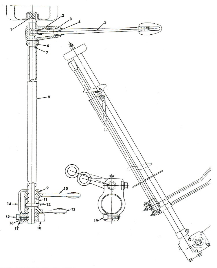 |
CONTROL SHAFT AND LEVERS
REMOVAL
- Disconnect low and reverse and second and high shifter rods at the control shaft levers by removing the cotter pins and flat washers.
- Remove the control lever fulcrum pin (4), Figure 13, control lever grommet (3), silencer 92) and take out control lever (5).
- Loosen the Allen screw (19) at the control shaft lower bracket attaching the (Handy Shift) control shaft to the steering jacket tube and slide the bracket and levers down on the tube approximately 2-1/4 inches to clear the control shaft pilot (1) at the steering jacket tube housing.
- Remove the screw 915), lockwasher (16), and plain washer (17) attaching the control shaft lever anchor bracket (14) to the control shaft lower bracket (18).
- While holding the control shaft (8) remove the second and high shift lever 913), control shaft drive pin retainer (11), drive pin (12), low and reverse shift lever (10), spring washer (9) and control shaft lever anchor bracket (18) from lower end of control shaft.
- Control shaft (8) and fulcrum bracket can now be removed by pulling the control shaft away from the jacket tube.
NOTE: Do not lsoe the pilot compression spring 96) and flat washer (7) when removing the control tube assembly.
INSTALLATION
- Install spring (6) and washer (7) into fulcrum bracket.
- Install fulcrum and shift control shaft over pilot (1).
- Install control lever silencer (2) and control lever grommet (3). Insert control lever through grommet, silencer, fulcrum bracket and in socket of pivot.
- Insert lock pin (4) using care not to damage fulcrum bracket.
- Place spring washer (9) low and reverse lever (10) on control shaft.
- Install drive pin 912) onto control shaft and retain in position with drive pin retainer (11).
- Slide anchor bracket (14), second and high lever (13) and control bracket lower (18). Install washer (17), external tooth lock washer (16) and hex head bolt (15).
NOTE Place gear shift lever in each shift position. Pin (11) must not bottom in groove of either lever in any gear shift position. If pin bottoms make necessary adjustments at anchor bracket (14).
as suggested in Hudson Service Merchandiser July 1954
When gear clashing or difficulty in shifting gears [are observed], the rods connecting the levers at the bottom of the Handy Shift Control with the transmission, should be adjusted as follows:
- Remove cotter pins and disconnect shift rod trunnions from ends of levers on control tube.
- Loosen cap screw (D) holding shift lever anchor bracket to control tube lower bracket. Press down on top of anchor bracket, compressing spring washer and tighten screw securely.
- Place hand control lever in neutral position (A). This is the crossover position in which the lever should be on inch above true horizontal position when measured at the end of knob.

- Check transmission and make sure low and reverse and second and high shifts (B) are in the neutral detents.
- Back off lock nuts (C) at trunnion on second and high shift rod and without disturbing position of hand control lever or transmission shift shaft, install trunnion in grommet at end of second and high lever. Tighten lock nuts, using care not to change length of rod.
- Adjust length of low and reverse shift rod so trunnion will enter in low and reverse lever grommet without disturing position of either the hand control lever or the transmission low and reverse shift shaft.
- Readjust if necessary, so hand control lever moves up and down freely in neutral position.
Q: I cannot find the fill or where to measure the fluid in the Hydra-Matic.
A: Hydra-Matic Transmission Refill is 10 Quarts. The level should be checked while engine is running. There's a manual available specifically for the Hydramatic engines which can be found through the H.E.T. Club or possible on eBay.
|
|
|
|
Courtesy HET JetSet - All Rights Reserved.
|
|