HudsonJet.net |  |
DISCLAIMER: Unless otherwise noted, service information has been provided by an edition of the Mechanical Procedures Manual, Body Manual, and the Hudson Owner Manual for Jet models. The data from the Manuals includes information covering specifications, adjustments and detailed operation involved in maintenance and repair procedures. After market updates from Hudson Service Merchandisers and other sources have been added as well and are credited in italics. HudsonJet.net provides this reference as a courtesy and is not responsible for any work done using Hudson Motor Car Company's publications or other sources provided on this site. |
|
WINDSHIELD and REAR WINDOW |
REMOVAL
- Remove windshield wiper arms and blades.
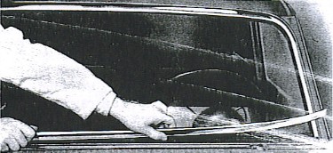
- Remove lower reveal moulding by pushing upward at either corner to release moulding lip from groove in weather strip, as shown in Figure 46.
- Remove moulding joint cover by prying up with a screw driver.
- Push downward to release both upper mouldings from the weatherstrip.
|
FIGURE 46
 |
INSTALLATION
NOTE: Apply a very light solution of liquid soap and water to the weatherstrip to facilitate installation.
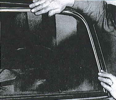
- Install the upper right and left mouldings first by pressing the lip of the mouldings into the lip join of the weatherstrip, as shown in Figure 47.
- Install the lower reveal moulding and moulding joint cover.
NOTE: It may be necessary to use a rubber mallet to facilitate the intallation of the reveal mouldings around the corners of the windshield. Use mallet carefully to avoid glass breakage.
- Replace wiper arms and blades.
|
FIGURE 47
 |
WINDSHIELD GLASS
REMOVAL
- Remove windshield reveal mouldings. "See Windshield Reveal Moulding Removal."
NOTE: Two types of weatherstrip are used interchangeably. One type uses a separate locking strip installed in the weatherstrip to exert rpessure against the glass and against the windshield opening pinchweld to form a positive seal. The other type has a built in locking and sealing design which requires no expander. With either type the locking and sealing pressure has to be released before removing the glass.
- Remove weatherstrip expander by prying out one end and then pull expander out of weatherstrip, as shown in Figure 48.
NOTE: To release the self locking tupe weatherstrip, insert a screw driver into the split joint and work the blade around the entire weatherstrip.
- Remove the rear view mirror and the self tapping metal screws attaching the garnish mouldings to the windshield opening.
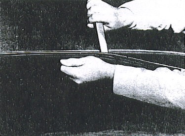
NOTE: To avoid breakage, a steady pressure should be maintained at the top center of the glass by a helper while the wedge is being worked to release the glass, Figure 49.
- Using a tapered fibre or hardwood block, insert the end of the wedge between the weatherstrip and the windshield glass; starting at the top of either corner and sliding the wedge across the top releasing the glass from the weatherstrip as shown in Figure 49.
- When glass is completely released from the top of the weatherstrip, lift glass out and away from body.
INSTALLATION
NOTE: With the weatherstrip properly in place over the windshield opening pinchweld brush the weaterstrip thoroughly with a solution of liquid soap and water before installing the new glass, as shown in Figure 50.
- With the aid of an assistant, insert the glass in the bottom opening of the weatherstrip an dusing a tapered piece of hardwood or fibre strip, start at the bottom of either side f windshield and while lifting up lip of the weatherstrip force the glass in place working the tapered block around the glass until the glass is completely enclosed in the weaterstrip channel, Figure 51.
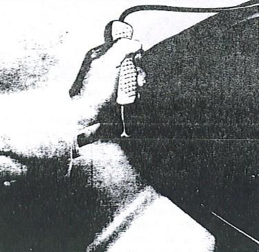
- Insert the weatherstrip expander into the channel of the weatherstrip starting at either lower corner and threading the expander around the entire glass, using Tool J-2767, Figure 52.
- Pull both ends of expander together and trim off any surplus to form a mitered joint.
NOTE: to lock the self-locking type weatherstrip, insert the blade of a screw driver into the interlock opening in weatherstrip and by exerting pressure downward, work the screw driver around the weatherstrip.
- Install windshield reveal mouldings, follow same procedure as outliner under "Windshield Reveal Moulding Installation".
- Position windshield garnish mouldings and rear view mirror, start all screws before tightening.
NOTE: Care must be taken to install the proper length moulding screws in order to avoid damage to the windshield glass or roof panel.
|
FIGURE 48
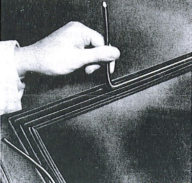 |
FIGURE 49
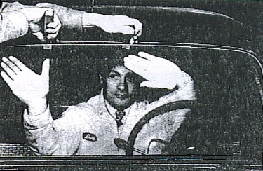 |
FIGURE 50
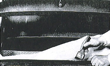 |
FIGURE 51
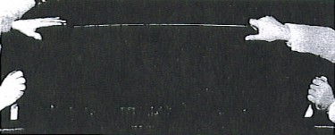 |
FIGURE 52
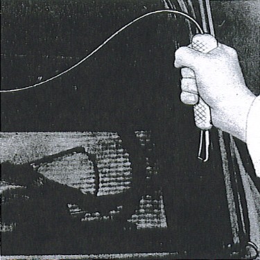 |
FIGURE 53
 |
WINDSHIELD WIPER - ALL Hudson Models 1951 thru 1954
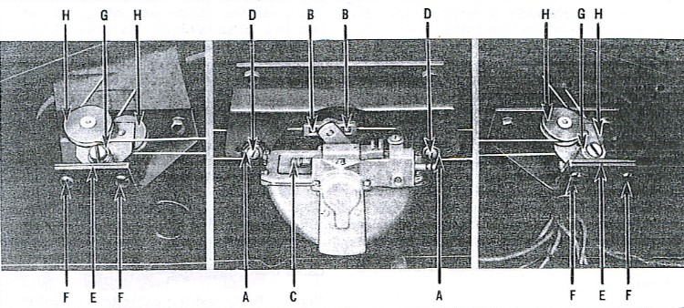
The windshield wiper mechanism consists of a vacuum operated motor assembly, two spring loaded cable tension assemblies, two pulley housing and cable assemblies, wiper arms, blades, and cables.
WINDSHIELD WIPER MOTOR ASSEMBLY
The windshield wiper motor assembly is mounted in the center of the dash under the hood. The motor is connected by cables to the wiper arms. A vacuum hose connects the wiper motor directly to the intake manifold or to a vacuum booster pump. The motor is controlled by a slide valve operated by a wire connected to the dash control
REMOVAL
- Disconnect pulley cables from the wiper motor at (B), Figure 53.
- Loosen retaining screw and remove control wire from slide.
- Disconnect vacuum hsoe from motor at (C).
- Remove two bolts (D) attaching wiper motor to mounting bracket and remove motor.
INSTALLATION
Reverse procedure of removal. Adjust cable tension and wiper arm travel.
PULLEY HOUSING AND CABLE ASSEMBLY
The windshield wiper pulley housing and cable assemblies, right and left, are inserted in the openings in the front cowl panel at the base of the windshield and are retained on the inside by a bolt and clamp. A burred bushing is provided for attachment and adjustment of the wiper arm. The small brass tube in each housing is for use with a windshield washer attachment.
REMOVAL
- Disconnect cables at the wiper motor and lift free of the tension assemblies.
- Remove wiper arms and blades. The wiper arms are retained on the burred bushings by a spring clip which is released by pulling the arm up and away from the windshield.
- Remove the bolt and clamp from the underside of the cowl panel.
NOTE: To remove right hand assembly, glove compartment must be removed to gain access to this bolt and clamp.
- Draw cables through dash to the inside of car.
- From the outside, lift out pulley housing and cables.
- Remove gasket.
INSTALLATION
Reverse procedure of removal. Adjust tension and wiper arm travel.
NOTE: Right and left pulley housing and cable assemblies differ slightly. See that small brass tube is on the inside of the assembly toward the center of the car.
CABLE TENSION PULLEY ASSEMBLY
Cable tension pulley assemblies (E), Figure 53, are mounted under the hood on the right and left side of the dash panel. These cable tension pulley assemblies are spring loaded to maintain approximately 14 pounds tension in the cables.
REMOVAL
- Disconnect cables from wiper motor at (B), Figure 53, and lift cables free from pulleys.
- Remove two screws (F) attaching assembly to support bracket and remove assembly.
INSTALLATION
Reverse procedure of removal and adjust cable tension.
NOTE: Right and left cable tension pulley assemblies are different. An identification mark is stamped on the top of the plate on which the pulleys are mounted.
|
ADJUSTMENT
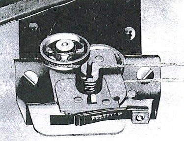
The pulley assemblies are spring loaded, Figure 54, and the cable instrument is automatic and should not require manual adjustment.
NOTE: If the control knob is in the full "On" position and the blade speed is slow, check the tension of the cables or check for a broken or partially plugged vacuum hose. Cable tension can be increased by pushing the tensioners outward advancing the tensioner to the next notch. Lubricate the pulley bearings with light engine oil. Apply Lubri-plate to the cables. Also check to see that cables are riding free.
|
FIGURE 54
 |

WINDSHIELD WASHER INSTALLATION
as suggested in Hudson Service Merchandiser July 1954
[Be sure to visit WiperMan.com, specializing in Trico Vacuum Wiper Motors. Excellent source for rebuilds, wiper arms, blades, etcetra!]
MOUNTING BRACKET
- The mounting bracket is mounted on the right (passenger) side of the car in the engine compartment on the fender shield. Use the bracket with two spacers as a drilling template in order to mount upright at the distance indicated from radiator brace. Drill two 7/32" upper holes to mount bracket and spacers with bolts, and one 9/64" lower hole for self-tapping screw. Mount bracket and insert pump and jar assembly.
- NOTE: On Jet Models, increase the bend in the bracket mounting tab to fit fender shroud. Spacers are not used for this installation.
HOSE CONNECTIONS
- Remove large knock out plug on firewall to right and below right cable tensioner, and small 3/4" knock out plug between wiper motor and cable tensioner and insert two grommets supplied in kit (See illustration.)
- NOTE: Do not remove large knock out plug on Jet Models, as large grommet is not used. Punch two holes to right of knock out plug just large enough to accomodate hoses.
- Connect small brass tee to the 15 inch and 32 or 23 inch lengths of 1/8" I.D. hose. connect each hose to tube extending down through cable housing under instrument panel, see illustration.
- Connect 3/16" I.D. hose (51 inch) to outer hose connection on jar marked "water" and feed through outside hole in double grommet or hole in firewall on Jet Models. Attach to remaining hose connection on small tee under instrument panel.
- Cut wiper hose 6 inches from wiper motor and insert "Y" connector. (See illustration.)
- Connect 3/16" I.D. hose (52 inch) to "Y" connector and insert through small single hole grommet in firewall. Attach this hose to shortest connection on wiper control.
- Connect remaining 3/16" I.D. hose (91 inch; cut to 67 inch for Jet Models) to center tube on washer marked "Vacuum," insert through remaining hole in large grommet or remaining hole in firewall, and attach to longest connection on wiper control.
|
|
REAR WINDOW GLASS
REMOVAL
NOTE: Two types of rear window weatherstrips are used interchangeably. One type uses a separate locking strip which is inserted in the groove of the weatherstrip and exerts pressure against the glass and the windshield opening pinchweld. The other type has a built-in locking and sealing design which requires no expander. With either type the locking and sealing pressure has to be released before removing the glass.
- Remove rear window reveal mouldings. See "Rear Window Reveal Moulding Removal."
- Remove the weatherstrip expander by prying out one end and then pull expander out of weatherstrip, Figure 66. To release the self locking type weatherstrip, insert a screw driver into the split joint and work the blade around the entire weatherstrip.
| FIGURE 66
 |
NOTE: Care must be taken when removing and installing tempered glass. Do not scratch the surface, scratching may cause the glass to disintegrate. The glass should not be hit with any tool if breakage is to be avoided.
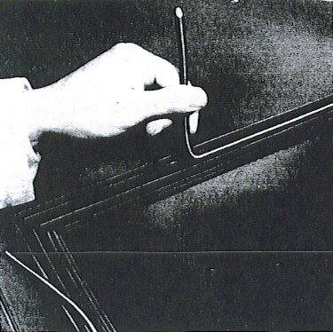
- With the aid of an assistant, start at the lower curved section on each side of the glass and insert a tapered fibre block between weatherstrip and behind the glass, as shown in Figure 67. Work wedge across the bottom, releasing glass from the weatherstrip. Grasp glass at bottom and lift glass up and away from body.
|
FIGURE 67
 |
INSTALLATION
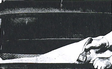
NOTE: Before installing the new glass, brush the weatherstrip thoroughly with a solution of liquid soap and water. Figure 68. |
FIGURE 68
 |
- With the aid of an assistant, enter the glass into both side openings of the weatherstrip and while pushing glass upward, use a tapered fibre block to open the cahnnel in the weatherstrip to enter the glass, Figure 69.
- After the glass has been entered at the top and side of weatherstrip, enter the tapered block between the weatherstrip and bottom of glass and carefully pull lip of weatherstrip channel over the glass until entire glass is seated in the weatherstrip channel.
- Insert the weatherstrip expander into the channel of the weatherstrip at either upper corner and thread the expander around the entire glass, using Tool J-2767, as shown in Figure 70. Pull both ends of expander together and trim off any surplus to form a mitered joint.
NOTE: To lock the self-locking type weatherstrip, insert the blade of a screw driver into the interlock opening in the weatherstrip and by exerting pressure downward, wor the screw driver around the weatherstrip, this procedure will interlock the weatherstrip.
- Install rear window reveal mouldings, follow procedure as oulined under "Rear Window Reveal Mouldings Installation."
| FIGURE 69
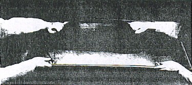 |
FIGURE 70
 |
REMOVAL
- Remove rear window glass. See "Rear Window Glass Removal."
- The weatherstrip is held in position over the pinchweld in the windsield opening by the compression action of the groove in the weatherstrip and can be removed by pulling the weatherstrip away from the windshield opening.
INSTALLATION
- With a tapered fibre tool, open up the groove of the weatherstrip and press weatherstrip over the rear window opening pinchweld, Figure 71.
- Reverse procedure on balance of installation.
|
FIGURE 71
 |
[ALL JET MODELS]
as suggested in Hudson Service Merchandiser Vol. 6, No. 7, July 1954
The expander for the rear window weatherstrip, 235799 [was] stocked and priced by the foot, therefore, when ordering for a single window [14 feet should have been specified]. (Not one piece.)
When ordering expander in any quantity [feet should have always been specified] in multiples of 14 as 28 ft., 42 ft., etc., as this part [was not] shipped in not less than 14 ft. and in multiples of 14 feet.
Note from webmaster: This may not be the case with all companies when ordering current day. I believe that K-Gap, for example, sells weatherstrip by the each.
|
Questions welcomed...
Answers coming soon...
Lo-Can Glass Int. no longer provides front windshields for Hudson Jets, however they can still be found, with your best bet being eBay. The PPG model number is DW309CL for clear glass and DW309GG for tinted glass (green along top couple inches).
Visit WiperMan.com, specializing in Trico Vacuum Wiper Motors. Excellent source for rebuilds, wiper arms, blades, etcetra!
|
|
|
|
Courtesy HET Jet Set - All Rights Reserved.
|
|