Hudson Jet |  |
DISCLAIMER: Unless otherwise noted, service information has been provided by an edition of the Mechanical Procedures Manual and Hudson Owner Manual for Jet models. The data from the Manuals includes information covering specifications, adjustments and detailed operation involved in maintenance and repair procedures. After market updates from Hudson Service Merchandisers and other sources have been added as well and are credited in italics. HudsonJet.net provides this reference as a courtesy and is not responsible for any work done using Hudson Motor Car Company's publications or other sources provided on this site. |
|
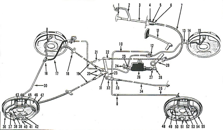 |
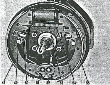
| FIGURE 1 - LEGEND |
- Hand brake lever grip
- Hand brake mounting bracket
- Hand brake ratchet rod
- Hand brake cable sleeve
- Hand brake cable retainer
- Hand brake dust grommet
- Hand brake cable
- Left rear wheel tube
- Brake tube connector
- Frame connector tube
- Brake pedal rod
- Front brake tee
- Bracket tube assembly
- Front brake hose connector
- Front brake hose assembly
- Rear axle brake tee
- Rear brake hose
- Rear brake cable support bracket
- Rear brake cables
- Rear brake clevis
- Brake cable return spring
- Brake cable clevis
- Brake cable lever
- Stop light switch
- Master cylinder outlet fitting
- Master cylinder assembly
- Master cylinder push rod
- Master cylinder clevis and pin
|
- Brake pedal lever
- Rear wheel brake tube
- Brake cable toggle assembly
- Cable lever pivot plate
- Cable lever brace clevis
- Cable lever pivot brace
- Right front brake tube
- Secondary shoe
- Adjusting eccentric
- Brake cable lever
- Brake hold down spring
- Anchor ramp
- Anchor spring
- Brake cable
- Brake shoe link
- Brake shoe pull back spring
- Wheel cylinder
- Primary shoe
- Brake backing plate
- Secondary shoe
- Adjusting eccentric
- Brake hold down spring
- Anchor ramp
- Anchor spring
- Wheel cylinder
- Brake pull back spring
- Primary shoe
|
|
Type
Drum Diameter
Material
Lining Type
Width - Front Shoes
Width - Rear Shoes
Thickness
Length Per Wheel
Front
Rear
Total Lining Area
Wheel Cylinder Size
Front
Rear
Adjustment
Pedal Free Play
Fluid Capacity | Bendix Fixed Anchor
9"
Centrifuse Iron
Moulded
2"
2" (Originally, the specs called for 1x3/4" on rear.)
.175"
17.475"
17.475"
132.14"
1-1/8"
15/16"
Eccentric Cam
1/4"
1-1/2 U.S. Pints |
|
The brake equipment is of the Bendix internal expanding, self-centering floating shoe type, hydraulically applied. Only minor adjustment is required as the shoes center themselves when the brakes are applied assuring uniform brake lining wear. Eccentrics contact the brake shoe ribs to provide adjustment to compensate for lining wear.
The maste cylinder is a combined reservoir and master cylinder with hydraulic pressure provided by foot edal and push rod operation. Displacement of fluid in the master cylinder conveys pressure through tubes and flexible hoses to the wheel cylinders.
Opposed wheel cylinder pistons contact the upper ends of the brake shoes. Pressure between the wheel cylinder pistons forces the brake shoes outward into contact with the brake drums.
Brake shoe retracting springs move the shoes inward when the hydraulic pressure ahs been relieved. As the shoes are retracted, the wheel cylinder pistons are moved toward the center of the cylinder. Hydraulic fluid displaced by the wheel cylinder piston retracting movement forces the fluid back through the tubes into the master cylinder reservoir.
Hand braking is provided through a pull type handle, operating a self locking hand control mechanism mounted below the instrument panel. Pulling back the hand brake lever applies the rear brakes mechanically for parking. Turning handle releases brakes.
Application is made easier by depressing the brake pedal in the usual manner, at the same time pulling upward on the brake handle. This relieves the load on the hand brake cables by hydraulically forcing the shoes against the brake drums. This prevents creation of a vacuum which might draw air into the cylinder piston cups when the shoes are expanded manually.
The brake master cylinder is a combined reservoir and master cylinder cast integrally. It maintains a constant volume of fluid in the hydraulic system at all times regardless of heat or cold expansion or contraction. It acts as a pump during bleeding operations.
It contains the fluid actuating piston, return spring, check valve and piston push rod that makes contact between the actuating piston and the brake pedal operating lever. Synthetic rubber primary and secondary cups are provided at each end of the piston. When extended, the push rod is enclosed in a synthetic rubber boot which serves to keep grit and dirt out of the hydraulic system. Intake and relief ports open into the reservoir.
|
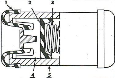
The piston (9), Figure 2, is returned to a released position much faster than the fluid returns to the master cylinder from the tube.
When piston (9) has been rapidly retracted, fluid flows from the reservoir (15) through by-pass port(12) into the cylinder. Pressure from the brake shoe retracting spring forces the wheel cylinders inward forcing fluid toward the master cylinder. The pressure exerted on the check valve (14) forces it off its seat permitting fluid to return to the master cylinder and through port (10) to the reservoir. A residual line pressure of 10 to 12 pounds is maintained in the tubes and wheel cylinders at all times by the check valve. This assures immediate braking upon application of pressure on the brake pedal.
|
FIGURE 2
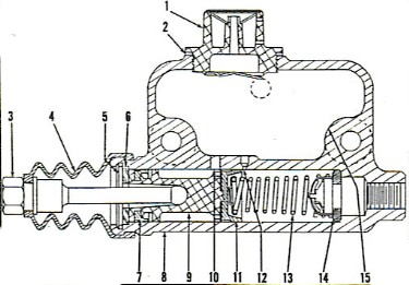 |
A clearance of 1/4" must be maintained between the end of the push rod (3), Figure 2 and the piston (9). If this clearance is not maintained, the piston cannot return sufficiently to uncover port (10) resulting in high line pressure and dragging brakes.
A diaphragm is incorporated in the stop light switch assembly mounted on the end of the master cylinder. Fluid pressure from the master cylinder against the diaphragm closes electrical contacts to operate the stop lights when the brake pedal is depressed. If the correct push rod clearance is not maintained and high line pressure results, the brake stop lights will continue to burn after the brake pedal has been released.
MASTER CYLINDER
REMOVAL
- Disconnect the stop light wires at the stop light switch, and the brake tubes at the master cylinder connector.
- Remove the brake pedal to push rod clevis pin (28), Figure 1, and disconnect the brake pedal retracting spring (22).
- Remove the two bolts attaching the master cylinder to the frame and remove the master cylinder.
REPAIR
- Thoroughly clean the exterior of the cylinder before disassembly.
- Remove the filler plug (1), Figure 2, and drain the brake fluid.
- Release the rubber boot (4) from the master cylinder groove, and remove the boot and push rod (3).
- Remove the retainer snap ring (5). This permits removal of the piston stop plate (6), piston (9), piston cup (11), spring (13), and check valve (14) for inspection and replacement if necessary.
NOTE: Do not use gasoline, kersone or carbon tetra-chloride for cleaning solution. Use clean alcohol only. Keep parts free from mineral oil of any kind.
INSPECTION
Inspect the master cylinder for light pitting or scratches. Hone the cylinder bore to restore the smooth bore necessary for efficient operation. After honing, the by-pass port (12) must be chamfered slightly to remove the burr.
Check the by-pass port to be certain it is unobstructed. Run a wire through the port to clear it of any foreign substances.
ASSEMBLY
- Wash all master cylinder parts in clean alcohol.
- After washing, dip all parts in "Hudson Hydraulic Brake Fluid" for lubrication.
- Install the check valve (14 and piston retrun spring (23). See Figure 2.
- Assemble the primary cup (11) and the piston assembly 99) and the piston stop plate (6).
NOTE: Always install new rubber cups.
- Install the retainer ring (5) in the master cylinder groove.
- Assemble the push rod (3) and the rubber boot assembly on the master cylinder.
- Refill the master cylinder to the required level with Filler Bottle J-713 using "Hudson Hydraulic Brake Fluid". Replace the filler plug.
NOTE: After removing the master cylinder or any hydraulic brake system parts, it is always necessary to bleed the system to expel any air that may have entered the system. Refer to "Bleeding Brake System".
|
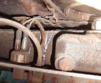
BRAKE LIGHT STOP SWITCH
See 24 in Figure 1. Your car might give you hints that this is going bad. One symptom is finding that the brake lights come on all by themselves. You get in, pump the brake pedal a couple times, and they go off. The next time you're in your garage, you'll find out that it wasn't a simple fix when you discover that the battery is dead. The lights came on again and you didn't catch it. One day, you won't be able to get the lights to come on at all when pressure is applied to the brake pedal. There is a diaphram within the switch that completes the connection when you step on the brake pedal and the pressure of the fluid presses the diaphram. The diaphram is probably sticking.
Without even testing the wiring for a short, it's visible on this one that the terminal on the left is badly corroded. The system may have very well blown a fuse as a result. This is an easily replaceable part and should be found out the local auto store.
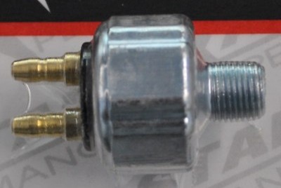 |
BAD SWITCH
 |
|
The wheel cylinders are of the straight bore type. Each wheel cylinder has two opposed positioned pistons (4), Figure 3, fitted with rubber cups (2). A spring (3) is assembled between the rubber cups to hold them against the pistons. Residual line pressure keeps the lips of the cups tight against the cylinder bores and pistons. The outer ends of the pistons contact the ends of the brake shoes to transmit outward force to the brake shoes. [Editor's Note: In the center of the rubber boot at each end you will see the steel button that the shoe web is in contact with when all is assembled on the backing (mounting) plate. This is part of what makes these cylinders somewhat unique. The piston serves as a guide to keep the "Cup" (2) straight in the bore and provides a solid surface for the shoe to contact. Although they don't mention it, they show the steel insert button in that drawing. Since the piston is made of Aluminum, it needs the hard steel contact piece at that point.] |
FIGURE 3
 |
REMOVAL
- Remove wheel and hub and drum assembly.
- Disconnect brake hose at frame bracket.
- Disconnect the brake shoe retracting spring.
- Remove the two wheel cylinder to backing plate attaching screws.
- Remove the wheel cylinder assembly with the flexible brake hose attached.
DISASSEMBLY
- Remove the wheel cylinder end guards (1), Figure 3.
- Remove brake cylinder pistons (4).
- Remove the piston cups (2).
- Remove the piston cup spring (3).
INSPECTION
Check the piston cups for frayed edges or swollen and distorted condition and the pistons for scores or scratches and pitting. Hone the cylinder bore if necessary to provide a smooth finish or replace as required.
ASSEMBLY
- Wash the wheel cylinder and all parts in clean alcohol.
- Dip the parts in "Hudson Hydraulic Brake Fluid" for lubrication.
- Assemble the spring (3), the piston cups (2), piston (4), and guards (1).
To install the wheel cylinder on the car, reverse the steps of removal.
- Tighten the screws attaching the wheel cylinder to the brake backing plate to 12 foot pounds torque using torque wrench J-1300.
|
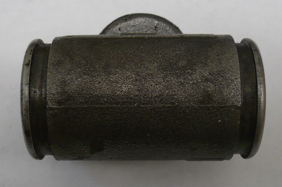
Bare Front Wheel Cylinder (without boots and bleeder valve)
 |
Editor's Note: It has been suggested that NAPA (United) Leftside #UP 36027 / Rightside #UP 36028 are replacement parts for the front wheel cylinders. This is not correct! (29405 is a casting number for both.) Although these are the same bore and similar in appearance, they are not a replacement for the original and will not fit. Although the cylinder may mount in the backing plate hole, the centerline of the cylinder bore is shifted substantially downward so that it will not align with the brake shoes. Further, but inconsequential, is the fact that the pistons are not the correct type. So, KEEP your original Front Wheel Cylinders for your Jet! It looks like we are stuck with having them sleeved if our originals aren't rebuildable by honing/kitting. Also, do not discard the original aluminum pistons as they have a steel "button" for direct shoe contact as opposed to the common "shoe-link" style piston. That applies to the rear cylinders as well.
 
A closer fit is the NAPA United #9004 & #9005 (L & R). It has all of the correct features, right down to those steel piston inserts ("buttons"). It mounts correctly and the offsets are exactly right, BUT it's a 1 inch bore. The result of using that cylinder would be an increase of about 25% in pedal effort to give the same stopping power at the front brakes and a disruption of the balance between front and rear axle braking effectiveness. The latter might be the dangerous part because the rear brakes would tend to lock up prematurely, possibly causing loss of control in a panic stop. I would not recommend use of that cylinder for that reason.
|
REMOVAL
- Remove the rear tire and wheel assembly.
- Install Hub Puller J-736 and remove the hub and drum assembly.
- Disconnect the wheel cylinder tube to wheel cylinder body.
- Disconnect the brake shoe retracting spring using tool J-142 Brake Spring Pliers and remove the cable lever link.
- Remove the two wheel cylinder to backing plate attaching screws.
- Remove the wheel cylinder.
NOTE: For complete disassembly, inspection and assembly, follow the procedure as outlined for servicing the front wheel cylinders.
To install the wheel cylinder on the car, reverse the steps of removal.
Tighten the screws attaching the wheel cylinder to the brake backing plate to 12 foot pounds torque.
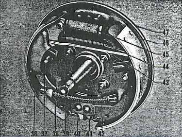
NOTE: The front brake assembly consists of the brake backing plate, Figure 4, the two brake shoes, wheel cylinder (53), brake shoe retracting spring (54), eccentric pins (49) and anchor spring (52). |
FIGURE 4
 |
DISASSEMBLY
- Remove the wheel and hub and drum assembly.
- Install Wheel Cylinder Clamp KMO-145 so to prevent the pistons or piston cups from being blown out if the brake pedal is depressed accidentally while the brake drum is off.
- Remove the brake shoe retracting spring using brake Spring Pliers J-142.
- Remove brake shoes and disconnect the anchor spring.
- Thoroughly clean away all dust and rust and apply Lubriplate grease to the shoe ramps on the backing plate, shoe ends and all frictional points.
Inspect the brake shoes for evidence of distortion and check to be sure that the lining is square with the brake drum surface.
Before installing the brake shoes, turn the eccentric pins inward as far as possible.
To install the brake shoes, reverse the steps of disassembly procedure.
|
REMOVAL
- Remove the rear tire and wheel assembly.
- Install Hub Puller J-736-A and pull the hub and drum assembly.
- Install wheel cylinder clamp KMO-145.
- Remove the brake shoe retracting spring (44), Figure 5, using brake Spring Pliers J-142.
- Remove the brake shoes (36) and (46), cable lever link (43), hand brake cable (42) and anchor spring (41).
- Thoroughly clean off all dust and rsut and apply Lubriplate grease to the shoe ramps on the backing plate, shoe ends and all frictional points.
|
FIGURE 5
 |
INSPECTION
Follow the same steps of shoe inspection as outlined for servicing front brakes. Click here to view.
To install the brake shoes follow the above removal in the reverse order.
Numerous rubber parts are used in the hydraulic system which makes necessary the use of brake fluids that are entirely free of mineral oil and other ingredients which are detrimental to the rubber and may cause swelling and early deterioration.
Maintain the level of the brake fluid not lower than 1/4" below the bottom of the master cylinder reservoir opening.
Hydraulic brake fluid must have a high boiling point to prevent evaporation and to prevent any tendency to vapor lock, yet at the same time, a good brake fluid must remain fluid at cold temperatures.
Mineral oil, in even the smallest quantity, should never be used. The slightest trace of mineral oil will destroy the sealing qualities of the rubber piston cups in two or three days. Never wash any hydraulic brake parts in gasoline as the slight amount of mineral oil present in gasoline will affect the rubber parts.
To detect the presence of mineral oil in the fluid, place a small quantity in a clear glass bottle. Separation of the fluid indicates the pressence of mineral oil.
Air in the braking system seriously impairs braking efficiency resulint in soft, spongy pedal action. It must, therefore, be removed by bleeding the lines if the fluid level has been allowed to get too low or any part of the braking system has been disconnected or replaced as follows:
NOTE: The bleeding operation should be performed at only one wheel cylinder at a time and repeated at other wheel cylinders if necessary. Start at the left front wheel and proceed to the right front, left rear, and right rear if required.
CAUTION: Do not depress the brake pedal while the brake drums are removed, unless a bleeder valve has been opened for bleeding brake lines. Remove dirt around master cylinder filler cap before removal for inspection of fluid level.
NOTE; If there is any doubt as to the grade of brake fluid present in the system, flush out the entire system with a good grade of clean alcohol.
- Fill "Master Cylinder Filler Bottle J-713" with genuine "Hudson Hydraulic Brake Fluid".
- Put nozzle in master cylinder reservoir. Open filler bottle valve before starting. This will keep master cylinder reservoir half full of fluid during the bleeding operation.
- Remove the bleeder screw from the end of the bleeder valve and attach J-628 Bleeder Tube. Insert the free end of the bleeder tube into a clean pint jar partly filled with brake fluid.
- Unscrew the bleeder valve at least three quarters of a turn and depress the foot pedal by hand, allowing the pedal to return to the released position slowly. This produced a pumping action which forced fluid through the tubing and out at the wheel cylinder carrying with it any air that may be present. After the brake pedal is depressed, it must be allowed to return slowly, otherwise air may be drawn into the system.
NOTE: The free end of the bleeder hose must be kept below the surface of the fluid in the pint jar.
Watch the flow of fluid from the hose and whel all air bubbles cease to appear, the bleeder screw should be closed tightly before taking the bleeder hose out of the container of fluid.
NOTE: Fluid withdrawn in any bleeding operation should not be used again.
Replenish fluid in the master cylinder after each cylinder is bled. If filler bottle J-713 (Filler and threaded Adapter) is used, this constant check on the master cylinder is not necessary because of its alrge capacity and the fact that the quantity is easily watched.
If the mastyer cylinder is drained during the bleeding operation, air will enter the system and the bleeding will have to be done over again at all four wheels.
When the bleeding operation is complete, the master cylinder must be refilled.
Check the fluid in the master cylinder every 1,000 miles.
REMOVAL
- Remove the nut and shakeproof washer holding the pedal rod to the brake pedal lever assembly.
- Remove pedal rod using Pedal Puller Tool J-2795 and washer.
- Remove the push rod clevis pin (28), Figure 1, disconnect the brake pedal pull back spring (21) and remove the master cylinder push rod (27).
- Remove the brake pedal retaining snap ring from the pedal shaft, and remove the brake pedal.
Check brake pedal bushings and replace if excessively worn.
To reassemble the brake pedal, reverse the steps outlined above.
BRAKE PEDAL ADJUSTMENT
The brake pedal lever (29), Figure 1, should have between 1/4" to 3/8" free play. (Measure at lower end of pedal lever (29). The free play is the movement of the pedal lever before the master cylinder push rod (27) contacts the master cylinder piston.
This adjustment is important to assure that the master cylinder piston returns to its normal position, otherwise the brakes will drag.
To adjust, loosen the push rod lock nut and increase or decrease the length of the push rod (27) until this free play of 1/4" to 3/8" is obtained.
After correct adjustment has been obtained, tighten the push rod lock nut, lubricate the pedal linkage and recheck free play.
HAND BRAKE LEVER ADJUSTMENT
The hand or parking brake applies the rear wheel brakes by brake cables connected to the hand brake lever and the rear brake shoe cable levers.
To adjust the parking or hand brake, pull the hand brake lever one notch outward from the fully released position.
Loosen the clevis lock nut, Figure 1.
Remove clevis pin (22) and shorten the brake cable (7) until a slight drag is felt at each rear wheel.
Tighten the lock nut and install cotter pin to secure clevis pin (22).
Release the hand brake lever fully and recheck rotation of the rear wheels. They should turn without any brake drag.
|
MINOR BRAKE ADJUSTMENT
NOTE: Brake drums should be at approximately room temperature when making brake shoe adjustments. If brakes are adjusted when the drums are hot and expanded, the shoes may drag when the drums cool and contract.
The floating shoe type brake assembly has shoes that center themselves in the drums when the brakes are applied. Therefore, the brake linings werar uniformly and no major brake adjustments are required.
- jack up all wheels, clear of the floor.
- Check and remove end play in wheel bearings if required.
- Check to see that the parking brake lever is fully released and the cable is not tight causing the brakes to drag slightly.
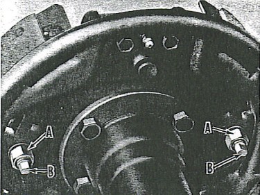
- Loosen the eccentric lock nut (A), Figure 6, on the rear of the backing plate.
- Rotate wheel in forwad direction and turn eccentric (B) downward until there is a heavy drag indicating complete lining contact with drum.
- Back the eccentric (B) off until the shoe is free to rotate the wheel without touching the drum. Tighten lock nut (A).
- The same procedure applies to the other 3 wheels.
|
FIGURE 6
 |
A thin film of Lubriplate grease should be placed on the brake shoe support ramp on the backing plate to combat rust and insure free brake shoe action.
NOTE: This lubrication should be done at the time of brake reline or adjustment, with hubs and rums removed and with brake cylinder clamps in place.
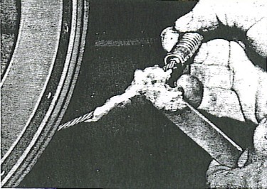
TO LUBRICATE BRAKE CABLES
- Disconnect clevis (20), Figure 1 and support bracket (18) at frame rail.
- Pull cable housing forward out of backing plate (snap-in type).
- Lubricate cable as in Figure 7, with viscous chassis lubricant, working housing back and forth to distribute lubricant.
- Push housing into backing plate and connect support bracket and clevis.
|
FIGURE 7
 |
BRAKE PEDAL GOES TO FLOORBOARD
- Normal wear of lining.
- improperly adjusted brake shoes.
- Leak in hydraulic system.
- Air in hydraulic system.
- No fluid in system.
ALL BRAKES DRAG
- Mineral oil in system.
- Porthole in master cylinder is closed.
ONE BRAKE DRAGS
- Brake shoe return spring is weak.
- Brake shoe set too close to the drum.
- Wheel cylinder cups distorted.
- Loose wheel bearings.
- Dirt in the brake line.
BRAKE PEDAL ACTION SPRINGY OR SPONGY
- Brake shoes improperly adjusted.
- Air in hydraulic system.
I need a source and part numbers for the brake hardware and springs for a Jet. I took apart and lost all the parts, so I have nothing to match it up to. Is Raybestos.com a good source?
Raybestos does offer quality products, however, you need to read the product description to ensure accuracy. Previous visits to that site have revealed that the brake parts they offer for Jets are the same as the ones they offer for the larger Hudson stepdowns, which are in fact not interchangeable. The Jet brakes are 9" - fronts and rears both 9" x 2", thickness .175". (Originally, the specs called for 2" front & 1x3/4" rear.) The brake equipment is of the Bendix self-centering floating shoe type. Only minor adjustment is required as the shoes center themselves when the brakes are applied assuring uniform brake lining wear. Eccentrics contact the brake shoe ribs to provide adjustment to compensate for lining wear. This is a completely different system from that used on the Hornet and Wasp vehicles. Please refer to the Replacement Parts List below for suitable brake system parts. Keep in mind that Jet parts cars are another source. The early Rambler & Willys Aero used the same brake system.
I need to do a brake job. I've read about a "dog bone" brake drum puller many times, but didn't keep the information. I've tried a regular puller that fit the lug bolts, with a big wrench, but can't get the drums to budge. My question is would someone direct me to the tech tip article someone wrote about the use of the "dog bone" puller, or give me an idea where I could rent one?
Be sure to check out the following tech page: Rear Wheel Puller. Both pictures and step-by-step directions are included!
|
Front Brake Hose: NAPA/United # 11190 (Central Auto Parts #F57819)
Rear Brake Hose: NAPA/United # 5784
Brake Shoes (Front and Rear) 9x2 Part No. RS-51
Master Cylinder: Wagner Lockheed cast # F2796 / MC2796, Neihof K2796 (Same as 61-66 Jeep Dispatcher)
Master Cylinder Rebuild Kit: NAPA 137, Raybestos MK137, Neihof K11300, also from Clifford's at 909-734-3310
Front Wheel Cylinder REBUILD KIT (2 per car): Wagner Lockheed #F71670, NAPA #UP 164, NAPA (United) #250
Shuck's/O'Reilly #wk164, Raybestos.com #wk164
|
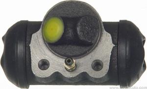
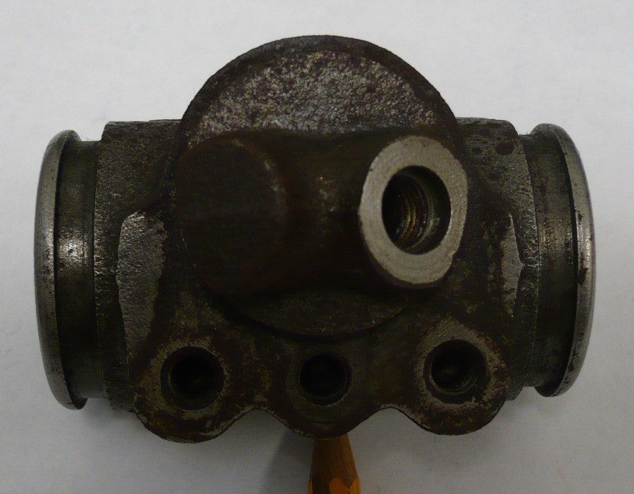
| Front Wheel Cylinder: Wagner Lockheed 1 1/8 bore: Front Left #F15427 / Front Right #F15428 for 1966 Jeep at RockAuto.com and REBUILD available through Hagens Auto Parts LH#15427/RH#15428 (Your core required, they rebuild with stainless steel sleeve.)
Pictured, Front Right #F15428 from Rock Auto. |
Wheel Seals, Front, Inner/Outer: Victor Seals 49466 and 134-9466
Rear Wheel Cylinder: Wagner Lockheed 15/16 bore: Wagner Lockheed #F38926, NAPA (United) #UP 36029,
Hagens Auto Parts #17073 (your core required, they rebuild with stainless steel sleeve)
Rear Wheel Cylinder REBUILD KIT (2 per car): Wagner Lockheed #F13677, NAPA #UP 170, NAPA (United) #250
Shuck's/O'Reilly #wk170, Raybestos.com #wk170
Lower Brake Shoe Return Spring (Also fits 53-66 CJ-3B, 5, M38A1) - Part #805602 on KaiserWillys.com
Upper Brake Shoe Return Spring (Also fits 41-66 MB, GPW, CJ-2A, 3A, 3B, 5, M38, M38A1) - Part #637905 on KaiserWillys.com
|
|
|
|
Courtesy HET JetSet - All Rights Reserved.
|
|