Hudson Jet |  |
DISCLAIMER: Unless otherwise noted, service information has been provided by an edition of the Mechanical Procedures Manual for Jet models. The data from the Manual includes information covering specifications, adjustments and detailed operation involved in maintenance and repair procedures. After market updates from Hudson Service Merchandisers and other sources have been added as well and are credited in italics. HudsonJet.net provides this reference as a courtesy and is not responsible for any work done using Hudson Motor Car Company's publications or other sources provided on this site. |
|
SPRINGS, SHOCK ABSORBERS AND STABILIZERS |
|
SPRINGS
| Front Springs | Rear Springs |
Type
Right Side
Load at Passenger Height
Rate
Height at Passenger Load
Free Height
Left Side
Load at Passenger Height
Rate
Height at Passenger Load
Free Height
Mounting
Heavy Scale Coil Spring
Load
Rate |
Coil
1850
376
9-15/16"
15"
1850
376
9-15/16"
15"
Rubber
Optional
1875
440 |
Type
Light Scale
Load Weight
Rate
Length and Width
Number of Leaves
Heavy Scale
Load Weight
Rate
Length and Width
Number of Leaves
Shackles
Spring Eye Dimension |
Semi-Elliptic
Standard
700
100
52"-1-3/4"
6
Optional
725
120
52"-1-3/4"
6
Silent "U" Threaded
.870 Rear, 1.125 Front |
SHOCK ABSORBERS
| Compressed Length |
Extended Length |
Front
Rear |
7-3/4"
12-1/16" |
12"
21-1/16" |
|
When the car does not seem level and a check of the coil spring height is desired, place the car so that the front end is level crosswise and then rock the car sidewise several times and allow the car to settle. This will remove any binding that might cause a dimension difference.
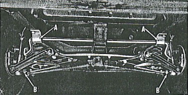
Measure the distance from the top of this lower support arm to the bottom of the upper rebound bracket, which should be 4-5/32" each side. (Curb load without passengers.) Shown at "B", Figure 1, Front Suspension.
If the two measurements vary more than 1/2" between sides, it is advisable to replace one or both coil springs.
NOTE: The high limit spring has Red Paint for identification and White Paint for low limit; these markings will be found at the bottom of the spring.
RIDING HEIGHT - REAR
Front wheel alignment is affected by weak rear springs or shock absorbers. To determine the riding height, measure the distance vertically from the top of the rear axle housing tube to the upper edge of the rear axle rubber bumper, Figure 8, Front Suspension. This distance should be 6-1/16" (Curb load - less passengers).
REMOVAL
- Raise the car until wheels are clear of floor and place jack stand under inner ends of the lower support arm.
- Remove wheel.
- Remove shock absorber upper palnut and stud nut.
- Remove shock absorbers lower mounting nuts and washers, turn shock absorber 1/4 turn and remove through opening in bottom of lower support arm.
- Remove lower support arm pivot to frame bolts, nuts and lockwashers.
- Carefully lower jack allowing coil spring to expand and remove the spring
CAUTION: The coil spring is under great pressure and care should be exercised when removing these springs.
INSTALLATION
- Install coil spring.
NOTE: Flat end of spring must be at top. Bottom must rest in lower support arm spring seat. Be sure silencer is in upper spring seat.
- Place jack under lower support arm compressing the spring. Use a drift to align holes in lower support pivot with corresponding holes in crossmember.
- Install lower support arm pivot attaching bolts and tighten securely.
- Install shock absorber in reverse order of removal.
REAR SPRINGS
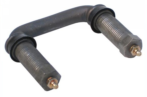
Rear springs are long leaf, semi-elliptical design. The front ends are attached to frame brackets with pivot bolts cushioned in rubber. (No lubrication is required at this point.) The rear ends of the springs are attached to the body frame rails through threaded self adjusting "U" type shackles operating in hardened steel, threaded bushings. The bushings are protected from road splash and dirt by rubber sleeve seals retained in position by the shoulders of the shackles before inserting the shackles in the bushings.
Rubber cushions and retainers are used between the spring mounting pad and spring to reduce road noise to a minimum.
NOTE: High limit springs are identified by two paint marks, low limit one paint mark, (located near the center bolt on lower spring leaf.)
|
REMOVAL
- Jack up the rear axle ona roller jack and place jack stands under the chassis fram side rails.
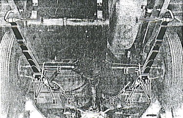
- With jack pressure under axle housing, disconnect lower end of shock absorber at spring mounting clip pad (A), Figure 1.
- Remove brake cable to spring retainer clip.
- Remove the rear spring shackle bushing (B) at rear spring eye and shackle.
- Remove bolt, nut and bushing (C) at front end of rear spring.
- Remove rear spring to axle clip nuts (D), washers, clip plates (F) and clips (E).
- Remove spring from car.
|
FIGURE 1
 |
ASSEMBLY
If the rear spring has been disassembled the leafs should be assembled in their proper order with a piece of 5/16" rod passing through the center bolt hole of each leaf. Do not lubricate spring equipped with inserts.
- Clamp the loose assembly in a vise and draw the leaves together, keeping them in alignment as the vise is tightened.
The bracket for holding the brake cable clip is assembled under the second from front leaf clip.
- Insert the center bolt and tighten the nut securely, replace the two wrap around clips and brake cable attaching clip.
NOTE: Spring inserts should be checked and replaced if necessary.
INSTALLATION
- Place rear spring in position on rear axle mounting pad.
- Insert one end of the spring rear shackle through the main leaf eye; after insuring the rubber seals are in place on the shackle start the threaded bushing on the shackle. DO NOT TIGHTEN.
- Install the front end of the spring and spring front bolt (rubber bushings in place).
- When proper alignment is obtained, attach nut and tighten securely.
NOTE: When tightening the mounting bolt, the rear spring should be mounted so that there is no unnatural twist set up in the rubber bushing. Squeaks at the rear spring front mounting bolts can be corrected by loosening nuts on rear spring front bolts and loosening nuts on rear spring front bolts and loading car with two or more passengers before pulling nuts up tight. DO NOT lubricate the rear spring front bushing.
- Install spring pads, mounting clips, nuts and washers. and tighten nuts to 75 to 80 pounds torque.
NOTE: It is important that spring clips be inspected at regular intervals and kept tight to insure against spring breakage.
- After mounting clip nuts have been properly torqued, finish tightening the rear shackle nut.
NOTE: It is important that the shackle be located properly to insure the bushing being threaded far enough on the shackle but not far enough to bottom the thread in the bushing as the shackle moves in its normal operation. Bottoming will cause a hard ride and shackle brekage. Spring shackles should be inspected periodically to make sure that they are tight but not binding.
- Install brake cable retaining clip on top of the spring.
- Attach lower end of shock absorbers to spring mounting clip pads.
- Lubricate the spring shackles and lower car.
|
The right hand rear spring shackle has right hand threads on both upper and lower ends; the left rear springs hackle has right hand threads on the upper end and left hand threads on the lower end.
The lower left hand shackle bushing is left hand thread and has an identification groove 1/16" wide on the head.
NOTE: If the zerk fitting is removed and replaced for any reason it must not be turned into the tapped hole so tightly as to cause the zerk fitting to bottom on the end of the shackle and thus loosen the plug that is in the end of the shackle housing.
|
See FIGURE 1, Letter B for placement of rear shackles.
 |
Use only viscous chassis lubricant at fittings. Springs without covers are equipped with inserts and must not be lubricated.
Direct double acting hydraulic type shock absorbers are used at the front and rear. The front shock absorbers are mounted axially within the front coil springs and are cushioned at the upper and lower ends in rubber grommets.
The rear units are identical in construction to the front units and are mounted diagonally for greatest efficiency and increased stability. At the upper end they are attached to the frame crossmember, while at the lower end they are assembled to the rear spring clip plates.
Both front and rear shock absorbers are non-serviceable and are not interchangeable. Defective units must be replaced.
Shock absorbers are available in either standard control or heavy control (Optonal).
The extra heavy duty control shock absorbers are available as an additional option.
NOTE: All shock absorbers have the part number and code stamped on the outside of the shock absorber.
SHOCK ABSORBER NOISE
When checking for noise, first determine that the noise is coming from shock absorbers and not from other sources.
Check the front shock absorber top nut with its palnut and that rubber bushings are tight and in good condition, also that the cap screws and nuts at the bottom of the front shocks are tight.
Noise that may develop in the rubber grommets can be eliminated by replacing the grommets and if the fit is tight, use a small amount of liquid soap at assembly.
REMOVAL
- Remove nut, palnut, and rubber bushing at the top of the shock absorber.
NOTE: Use an offset screw driver to prevent the stem from turning and a 9/16" open end wrench to remove the nut.
- Remove the two cap screws holding the shock absorber lower support plate to the lower support arm.
- Turn the shock absorber a quarter turn and remove.
NOTE: To install, reverse procedure of removal. Check condition of the grommets.
|
REMOVAL
- Remove lower stud nut, palnut, and retainer at rear spring clip plates, Figure 2.
- At rear compartment remove two Phillip head screws retaining the rear shock absorber access hole cover.
- Remove upper mounting stud nut, palnut and retainer "B".
- Remove shock absorber.
INSPECTION
- Check condition of grommets and replace if worn.
- Mount shock absorbers in a vise being careful that the larger tube is at the upper end. Move up and down by hand. After six or eight strokes, the unit should be primed. A noticeable lag or lack of resistance is an indication of a faulty unit which should be replaced.
NOTE: Assemble shock absorber with stone shield to front of the car.
INSTALLATION
To install, reverse procedure of removal.
|
FIGURE 2
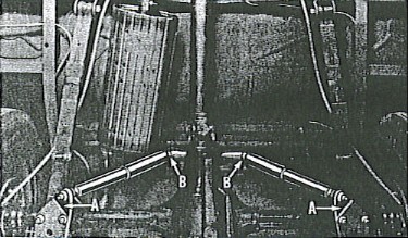 |
Stabilizer control is by a specially designed bar which is attached to the frame side member, Figure 3. The ends of the bar are directed toward the rear to form lever arms and the lever arms are attached to the stabilizer bar connectors which in turn are attched to the lower support arm.
The stabilizer is mounted in rubber bushings, and requires no lubrication.
REMOVAL
- Remove nuts and lockwashers from bottom of stabilizer connectors (B).
- Remove two bolts from brackets to frame (each side) (A) and remove stabilizer.
NOTE: To install, reverse procedure of removal and make sure the stabilizer is properly centralized.
|
FIGURE 3
 |
Front Shocks: NAPA Regal Ride 1126
Rear Shocks: Monroe #5601024, NAPA Regal Ride 1128, Central Auto Parts (EA 31125) 407-422-9851
Shocks: NAPA # NS 555001. Dimensionally correct (within reason), but is billed as an "RV" shock absorber, intended for retro-fits to trailers. Although I don't know how they will act on a Jet, I bet they'll be fine. They are somewhat more expensive and I'll bet your local store doesn't have them in stock but they can get them.
|
|
|
|
Courtesy HET JetSet - All Rights Reserved.
|
|